


10/100 Non-PCI Ethernet Single Chip MAC + PHY
Datasheet
SMSC LAN91C111 REV C 19 Revision 1.91 (08-18-08)
DATASHEET
Chapter 6 Signal Description Parameters
This section provides a detailed description of each SMSC LAN91C111 signal. The signals are
arranged in functional groups according to their associated function.
The ‘n’ symbol at the beginning of a signal name indicates that it is an active low signal. When ‘n’ is
not present before the signal name, it indicates an active high signal.
The term “assert” or “assertion” indicates that a signal is active; independent of whether that level is
represented by a high or low voltage. The term negates or negation indicates that a signal is inactive.
The term High-Z means tri-stated.
The term Undefined means the signal could be high, low, tri-stated, or in some in-between level.
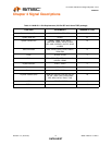
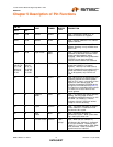
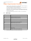
6.1 Buffer Types
DC levels and conditions defined in the DC Electrical Characteristics section.
O4 Output buffer with 2mA source and 4mA sink
O12 Output buffer with 6mA source and 12mA sink
O16 Output buffer with 8mA source and 16mA sink
O24 Output buffer with 12mA source and 24mA sink
OD16 Open drain buffer with 16mA sink
OD24 Open drain buffer with 24mA sink
I/O4 Bidirectional buffer with 2mA source and 4mA sink
I/O24 Bidirectional buffer with 12mA source and 24mA sink
I/OD Bidirectional Open drain buffer with 4mA sink
I Input buffer
IS Input buffer with Schmitt Trigger Hysteresis
Iclk Clock input buffer
I/O Differential Input
O/I Differential Output
** 5V tolerant. Input pins are able to accept 5V signals