


10/100 Non-PCI Ethernet Single Chip MAC + PHY
Datasheet
SMSC LAN91C111 REV C 71 Revision 1.91 (08-18-08)
DATASHEET
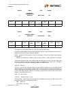
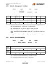
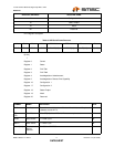
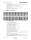
PHY Register Description
D[15:0]
↓
Register 0 Control
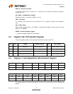
Register 1 Status
Register 2 PHY ID#1
Register 3 PHY ID#2
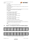
Register 4 AutoNegotiation Advertisement
Register 5 AutoNegotiation Remote End Capability
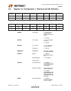
Register 16 Configuration 1
Register 17 Configuration 2
Register 18 Status Output
Register 19 Mask
Register 20 Reserved
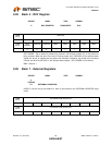
17 Configuration 2
18 Status Output
19 Mask
20 Reserved
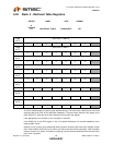
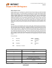
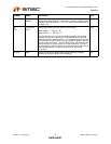
Table 9.1 MII Serial Frame Structure
<Idle> <Start> <Read> <Write> <PHY Addr.> <REG.Addr.> <Turnaround> <Data>
IDLE ST[1:0] READ WRITE PHYAD[4:0] REGAD[4:0] TA[1:0] D[15:0]
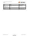
SYMBOL NAME DEFINITION R/W
IDLE Idle Pattern These bits are an idle pattern. Device will not initiate an MI cycle until
it detects at least 32 1's
W
ST1
ST0
Start Bits When ST[1:0]=01, a MI Serial Port access cycle starts. W
READ Read Select 1 = Read Cycle W
WRITE Write Select 1 = Write Cycle W
PHYAD[4:0] Physical
Device
Address
PHYSICAL ADDRESS R
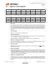
REGISTER ADDRESS REGISTER NAME