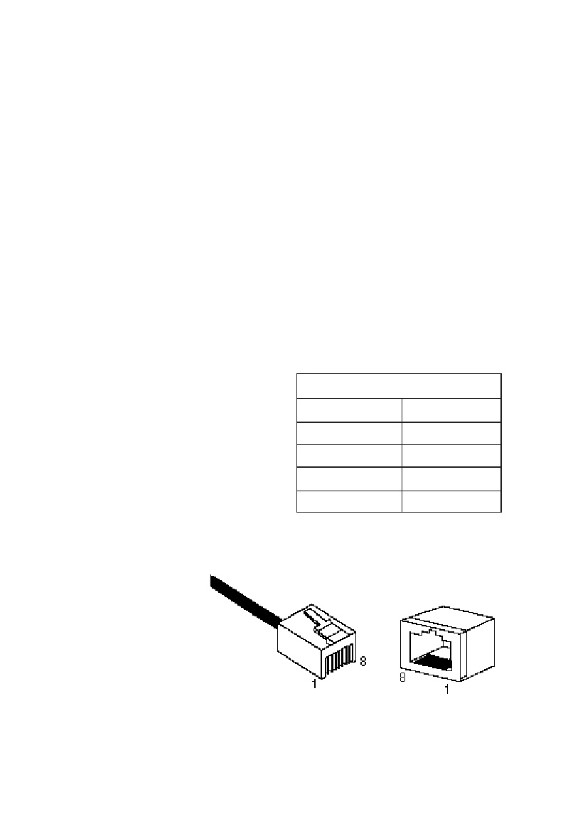
10BASE-T/100BASE-TX Pin Assignments
Caution: Regulations regarding the connection of equipment
to telephone networks vary from country to country.
Check with your local telephone network supplier
before using existing telephone wiring.
An Ethernet twisted-pair link segment requires two pairs of
wires. Each wire pair is identified by two different colors. For
example, one wire might be green and the other, green with
white stripes.
Caution: Each wire pair must be attached to the RJ-45 connec-
tors in a specific orientation (See “Cabling
Guidelines” in Chapter 4 for an explanation.)
Each twisted-pair link segment
must have an RJ-45 connector
attached to both ends.
According to the IEEE specifi-
cations, pins 1 and 2 are used
for transmitting data, and pins
3 and 6 for receiving data.
* The “+” and “-” signs are used to represent the polarity of the wires
that make up each wire pair.
Note how the
pins are num-
bered. Be sure
to hold the con-
nectors in the
same orientation
when attaching
the wires to the
pins.
A-3
CABLES
Pin Number Assignment*
1 Tx+
2 Tx-
3 Rx+
6 Rx-
RJ-45 Pin Assignments
Figure A-1. RJ-45 Connector Pin Numbers


