


2-4 Ultra Enterprise 6000/5000/4000 Systems Installation Guide—November 1996
2
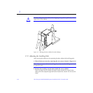
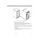
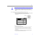
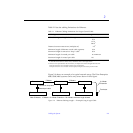
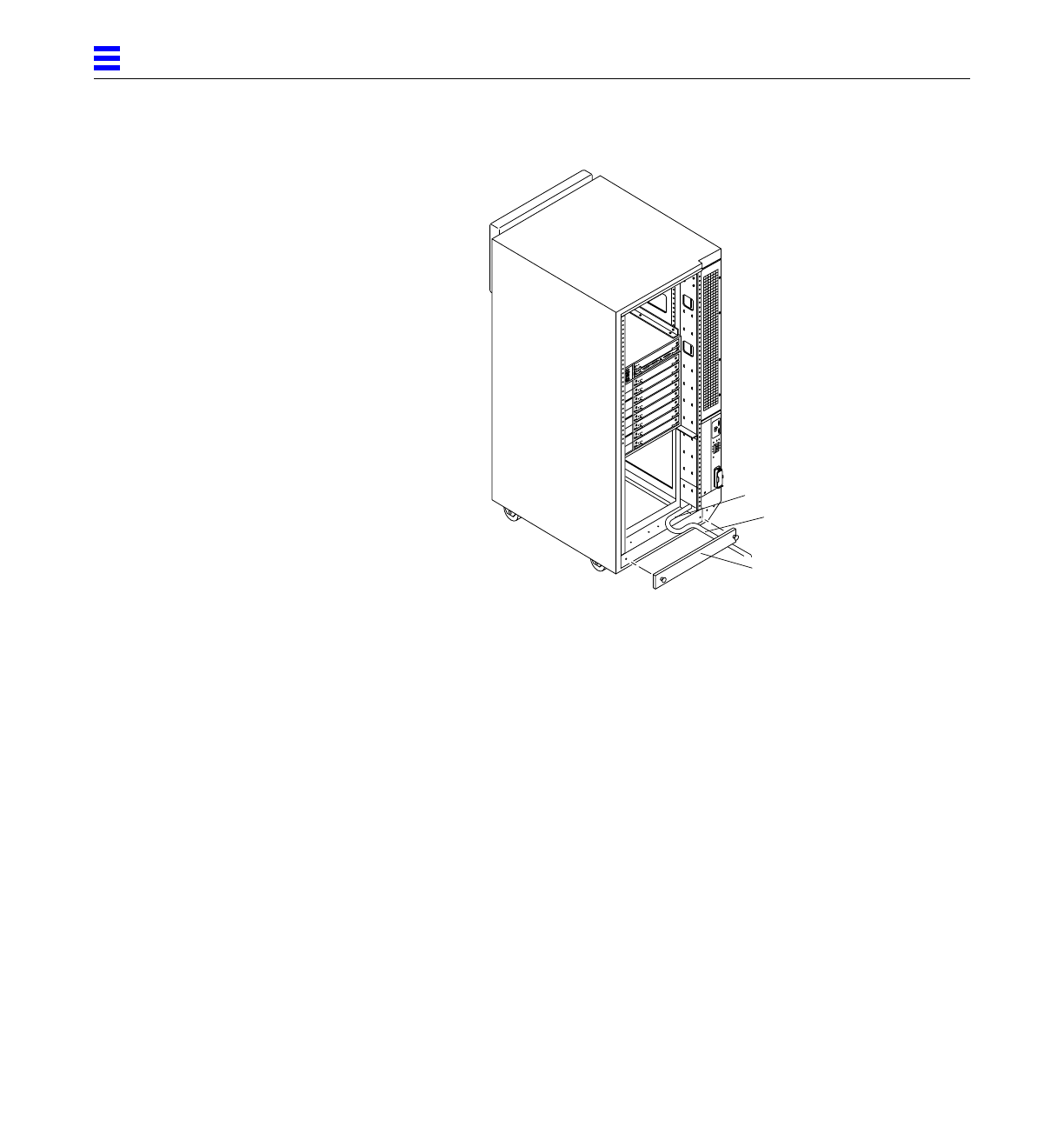
Figure 2-3 Routing Cables Under the Kick Panel
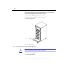
2.3 Connecting the Power Cords
2.3.1 Connecting the Enterprise 6000/5000 System Power Cord
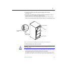
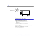
1. Remove the rear screen and the kick panel.
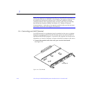
See Section 2.2, “Removing and Replacing the Enterprise 6000/5000 Cabinet
Rear Screen and Kick Panel.”
2. Route the AC power cord and external interface cables along the bottom
panel of the cabinet and over the edge of the bottom panel.
See Figure 2-3. The cables should be between the bottom panel and the kick
panel when you replace the kick panel.
3. Uncoil the AC power cord and plug it into a grounded wall outlet.
The outlet must be a 200-240 VAC 30A circuit, dedicated solely to the server
cabinet, as described in the site preparation instructions in Chapter 1.
Kick panel
Cable
Bottom panel