


5-12
AS1011M-T2 User's Manual
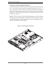
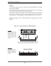
5-9 Connector Defi nitions
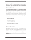
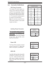
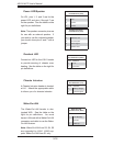
ATX Power Connector
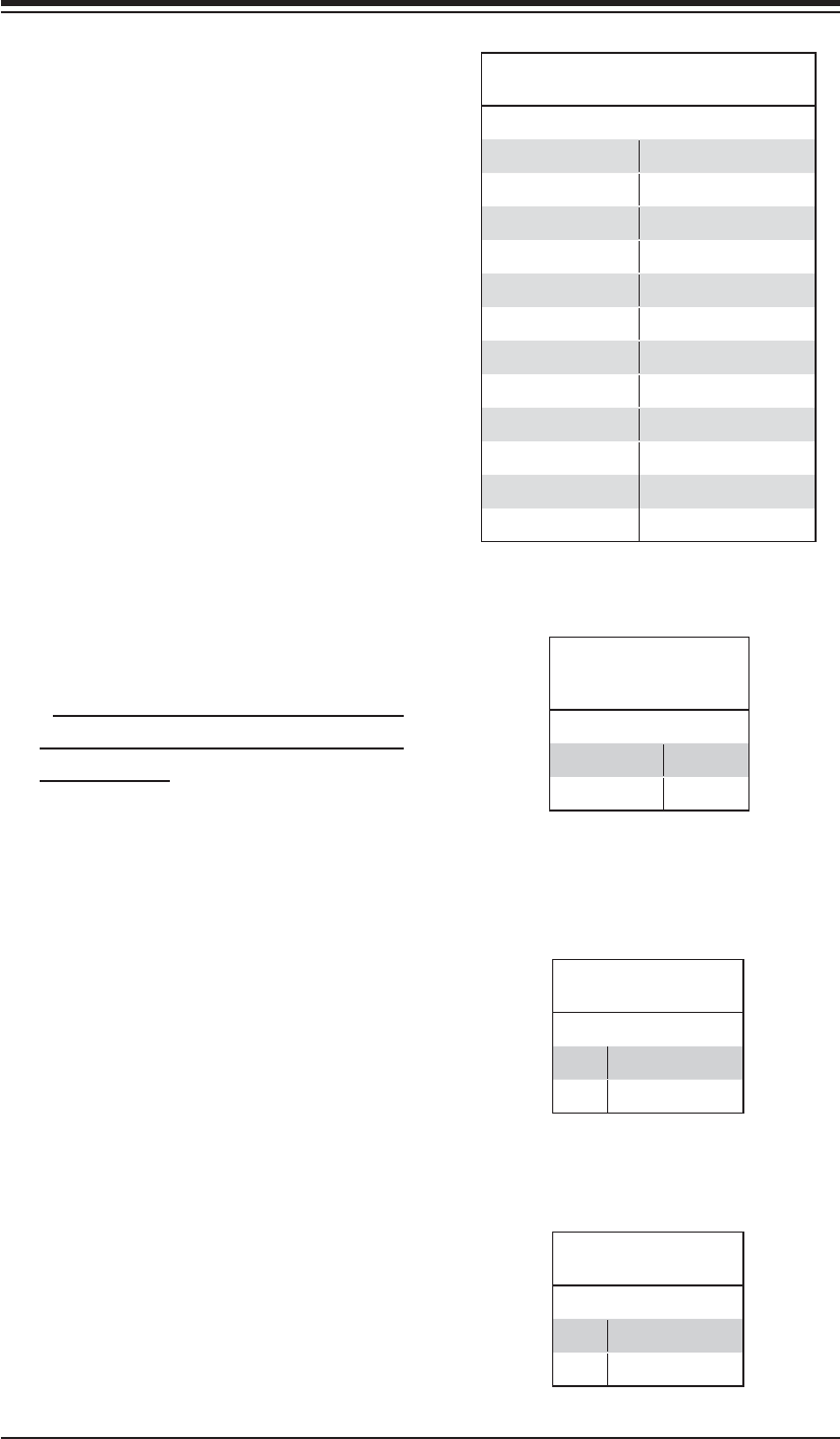
The primary ATX power supply con-
nector (J1B1) meets the SSI (Super-
set ATX) 24-pin specifi cation. Refer to
the table on the right for the pin defi ni-
tions of the ATX 24-pin power connec-
tor. This connection supplies power to
the chipset, fans and memory.
Note: You must also connect the 4-pin
(J22) power connector to your power
supply (see below).
ATX Power 24-pin Connector
Pin Defi nitions (J1B1)
Pin# Defi nition Pin # Defi nition
13 +3.3V 1 +3.3V
14 -12V 2 +3.3V
15 COM 3 COM
16 PS_ON 4 +5V
17 COM 5 COM
18 COM 6 +5V
19 COM 7 COM
20 Res (NC) 8 PWR_OK
21 +5V 9 5VSB
22 +5V 10 +12V
23 +5V 11 +12V
24 COM 12 +3.3V
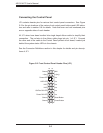
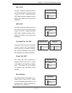
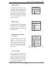
Auxiliary Power Connector
The 4-pin auxiliary power connector at
J22 must also be connected to your
power supply. This connection sup-
plies extra power that may be needed
for high loads. See the table on the
right for pin defi nitions.
Required Connection
Auxiliary Power
Connector
Pin Defi nitions (J22)
Pins Defi nition
1 & 2 Ground
3 & 4 +12V
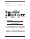
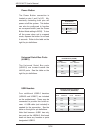
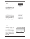
Power LED
The Power LED connection is located
on pins 15 and 16 of JF1. Refer to the
table on the right for pin defi nitions.
Power LED
Pin Defi nitions (JF1)
Pin# Defi nition
15 Vcc
16 Control
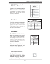
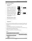
HDD LED
The HDD (IDE Hard Disk Drive) LED
connection is located on pins 13 and
14 of JF1. Attach the IDE hard drive
LED cable to display disk activity.
Refer to the table on the right for pin
defi nitions.
HDD LED
Pin Defi nitions (JF1)
Pin# Defi nition
13 Vcc
14 HD Active