


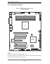
5-14
AS1011M-T2 User's Manual
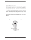
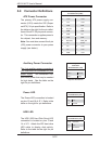
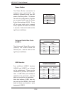
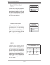
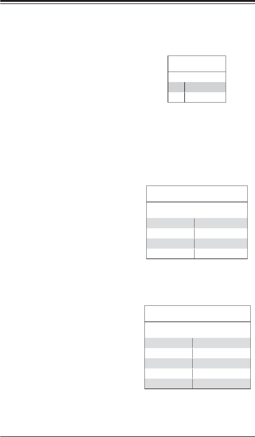
Power Button
The Power Button connection is
located on pins 1 and 2 of JF1. Mo-
mentarily contacting both pins will
power on/off the system. This button
can also be confi gured to function
as a suspend button (see the Power
Button Mode setting in BIOS). To turn
off the power when set to suspend
mode, depress the button for at least
4 seconds. Refer to the table on the
right for pin defi nitions.
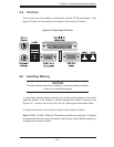
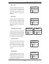
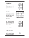
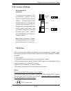
Universal Serial Bus Ports
(JUSB1)
The Universal Serial Bus ports
(USB2.0) are located beside the
LAN1/2 ports. See the table on the
right for pin defi nitions.
Power Button
Pin Defi nitions (JF1)
Pin# Defi nition
1 PW_ON
2 Ground
Universal Serial Bus Ports
Pin Defi nitions (JUSB1)
USB0
Pin # Defi nition
USB1
Pin # Defi nition
1 +5V 1 +5V
2PO- 2PO-
3PO+ 3PO+
4 Ground 4 Ground
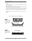
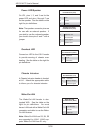
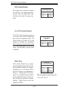
USB Headers
Four additional USB2.0 headers
(USB4/5 and USB6/7) are included
on the motherboard. These may be
connected to provide front side ac-
cess. A USB cable (not included) is
needed for the connection. See the
table on the right for pin defi nitions.
Note that because JUSB1 has only
two ports on the H8SMi-2, this board
does not have any headers or ports
designated USB2/3.
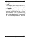
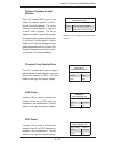
Universal Serial Bus Headers
Pin Defi nitions (USB4/5/6/7)
USB2
Pin # Defi nition
USB3/4
Pin # Defi nition
1 +5V 1 +5V
2 PO- 2 PO-
3 PO+ 3 PO+
4 Ground 4 Ground
5 Key 5 No connection