


5-18
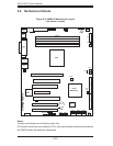
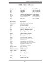
AS1011M-T2 User's Manual
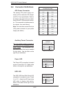
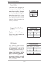
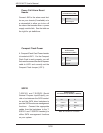
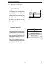
Power Fail Alarm Reset
Header
Connect JAR to the alarm reset but-
ton on your chassis (if available) or to
a microswitch to allow you to turn off
the alarm that sounds when a power
supply module fails. See the table on
the right for pin defi nitions.
Alarm Reset Header
Pin Defi nitions (JAR)
Pin# Defi nition
1 Ground
2 Reset Signal
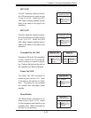
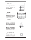
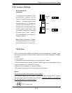
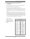
Compact Flash Power
A Compact Flash Card Power header
is located at JWF1. For the Compact
Flash Card to work properly, you will
fi rst need to connect the device's power
cable to JWF1 and correctly set the
Compact Flash Jumper (JCF1).
Compact Flash
Power Header
Pin Defi nitions (JWF1)
Pin# Defi nition
1+5V
2 Ground
3 Signal
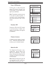
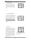
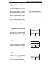
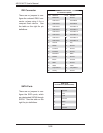
SGPIO
T-SGPIO1 and T-SGPIO2 (Serial
General Purpose Input/Output) pro-
vide a bus between the SATA control-
ler and the SATA drive backplane to
provide SATA enclosure management
functions. Connect the appropriate
cables from the backplane to the T-
SGPIO1 and T-SGPIO2 header(s) to
utilize SATA management functions
on your system.
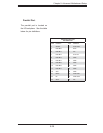
SGPIO Headers
Pin Defi nitions (T-SGPIO1, T-SGPIO2)
Pin# Defi nition Pin # Defi nition
1NC 2NC
3 Ground 4 Data
5 Load 6 Ground
7NC 8NC
Note: NC indicates no connection.