


Chapter 5: Advanced Motherboard Setup
5-19
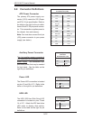
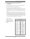
5-10 Jumper Settings
Explanation of
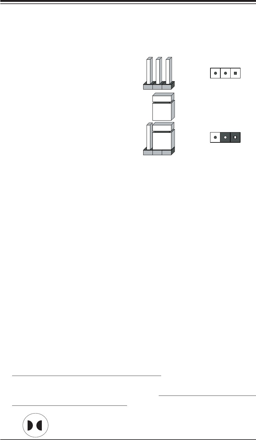
Jumpers
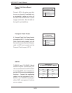
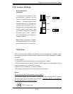
To modify the operation of the
motherboard, jumpers can be
used to choose between optional
settings. Jumpers create shorts
between two pins to change the
function of the connector. Pin 1 is
identifi ed with a square solder pad
on the printed circuit board. See
the diagram at right for an example
of jumping pins 1 and 2. Refer to
the motherboard layout page for
jumper locations.
Note: On two-pin jumpers, "Closed"
means the jumper is on and "Open"
means the jumper is off the pins.
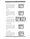
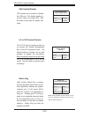
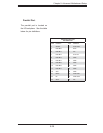
CMOS Clear
JBT1 is used to clear CMOS and will also clear any passwords. Instead of pins,
this jumper consists of contact pads to prevent accidentally clearing the contents
of CMOS.
To clear CMOS,
1) First power down the system and unplug the power cord(s).
2) With the power disconnected, short the CMOS pads with a metal object such as
a small screwdriver for at least four seconds.
3) Remove the screwdriver (or shorting device).
4) Reconnect the power cord(s) and power on the system.
Notes:
Do not use the PW_ON connector to clear CMOS.
The onboard battery does not need to be removed when clearing CMOS, however
you must short JBT1 for at least four seconds. Clearing CMOS on the H8SMi-2
will not reset the RTC (real-time clock).
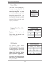
Connector
Pins
Jumper
Setting
321
321
JBT1 contact pads