


Chapter 5: Advanced Motherboard Setup
5-1 Handling the Motherboard ............................................................................... 5-1
5-2 Mounting the Motherboard into a Chassis ...................................................... 5-2
5-3 Processor and Heatsink Installation ................................................................ 5-2
5-4 Connecting Cables .......................................................................................... 5-5
Connecting Data Cables ........................................................................... 5-5
Connecting Power Cables ......................................................................... 5-5
Connecting the Control Panel ................................................................... 5-6
5-5 I/O Ports ......................................................................................................... 5-7
5-6 Installing Memory ............................................................................................. 5-7
5-7 Adding PCI Cards ............................................................................................ 5-9
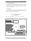
5-8 Motherboard Details ..................................................................................... 5-10
H8SMi-2 Layout ....................................................................................... 5-10
H8SMi-2 Quick Reference ...................................................................... 5-11
5-9 Connector Defi nitions .................................................................................... 5-12
ATX Power Connector .......................................................................... 5-12
Auxiliary Power Connector ...................................................................... 5-12
Power LED .............................................................................................. 5-12
HDD LED .............................................................................................. 5-12
NIC1/NIC2 LED ...................................................................................... 5-13
Overheat/Fan Fail LED .......................................................................... 5-13
Power Fail LED ...................................................................................... 5-13
Reset Button ......................................................................................... 5-13
Power Button ......................................................................................... 5-14
Universal Serial Bus Ports ..................................................................... 5-14
USB Headers ......................................................................................... 5-14
ATX PS/2 Keyboard and Mouse Ports .................................................... 5-15
Serial Ports .............................................................................................. 5-15
Fan Headers ............................................................................................ 5-15
LAN1/2 (Ethernet Ports) ......................................................................... 5-15
Power LED/Speaker ............................................................................... 5-16
Overheat LED ........................................................................................ 5-16
Chassis Intrusion .................................................................................... 5-16
Wake-On-LAN .......................................................................................... 5-16
Wake-On-Ring ........................................................................................ 5-17
SMBus Header ....................................................................................... 5-17
Redundant Power Supply Fail Header .................................................. 5-17
UID LED Header .................................................................................... 5-17
vii
Table of Contents