


Chapter 5: Advanced Motherboard Setup
5-21
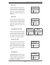
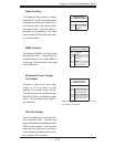
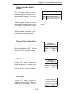
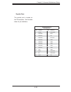
Onboard Speaker Enable/
Disable
The JD1 header allows you to use
either an external speaker or the in-
ternal (onboard) speaker. To use the
internal onboard speaker, close pins
6 and 7 with a jumper. To use an
external speaker, remove the jumper
and connect the speaker wires to pins
4 (+5V) and 7 (control signal). See the
table on the right for settings and the
table associated with the Power LED/
Keylock/Speaker connection (previ-
ous section) for jumper settings.
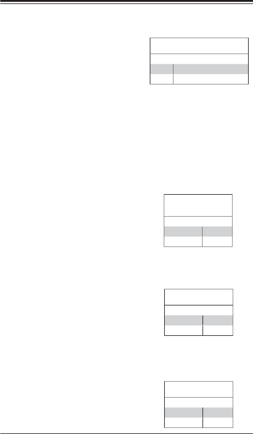
Onboard Speaker Enable/Disable
Pin Defi nitions (JD1)
Pins Defi nition
6 and 7 Jump for onboard speaker
4 and 7 Attach external speaker wires
Note: Pins 4-7 are used only for the onboard
speaker.
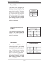
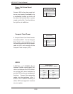
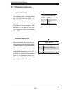
Compact Flash Master/Slave
The JCF1 jumper allows you to assign
either master or slave status a compact
fl ash card installed in IDE1. See the
table on the right for jumper settings.
Compact Flash
Master/Slave
Jumper Settings (JCF1)
Jumper Setting Defi nition
Closed Master
Open Slave
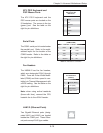
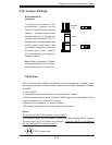
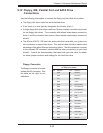
USB Power
Jumper J24 is used to choose the
power source for all USB ports and
headers on the motherboard. See the
table on the right for jumper settings.
USB Power
Jumper Settings (J24)
Jumper Setting Defi nition
Pins 1-2 P5V Dual
Pins 2-3 P5V
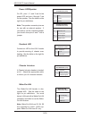
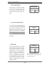
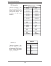
PS2 Power
Jumper J18 is used to choose the
power source for all PS/2 devices at-
tached to the motherboard. See the
table on the right for jumper settings.
PS2 Power
Jumper Settings (J18)
Jumper Setting Defi nition
Pins 1-2 P5V Dual
Pins 2-3 P5V