


2-10
X8DTU-6F+/X8DTU-6TF+/X8DTU-6(T)F+-LR User’s Manual
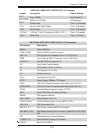
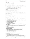
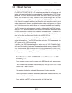
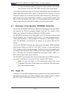
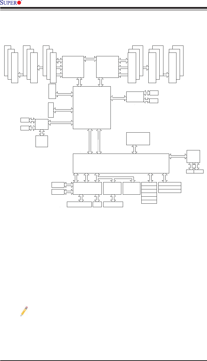
System Block Diagram
Note: This is a general block diagram and may not exactly represent the
features on your motherboard. See the Motherboard Features pages for
the actual specifi cations of each motherboard.
Processor#1
QPI
DDR3 DIMM
C
A
B
D
E
F
DDR3 DIMM
DDR3 DIMM
DDR3 DIMM
DDR3 DIMM
DDR3 DIMM
B
C
E
F
BMC
VGA Connection
ESI
SPI
BIOS
CLINK
CLINK
PCIE Port 1-4
PCI-E x16
Gen2 x4
Gen2 x8
ICH10R
ESI
IOH
36D
PORT1
PORT
1,2
5,6
PCI-E x4
in x8 Slot
PORT
RJ45
COM1
COM2
SIO
PS2 KB/MS
USB 0/1
USB
QPI
QPI
PORT
8,10
SATA #2
SATA #3
SATA #4
SATA #5
SATA #0
SATAPCI
USB
TPM
LPC
PORT1
Gen2 x16
PORT
7, 8, 9,10
Intel
RJ45 RJ45
Gen1 x4
PCIE Port 5-6
Processor#0
SATA #1
USB 4/5
USB 6, 7
PORT0
PORT0
PORT1
PORT
3,4
PORT0
(Lane Reversal)
SAS 2108
LSI
Optional BBU
I-PASS
I-PASS
512 MB
800 MHz
DDR2
Gen2 x8
Intel
82599EB
10Gb
SFP+
SFP+
82576EB
SLB9635TT
1.2
W83527HG