


Chapter 3: Installation
3-39
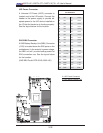
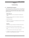
JPI2C1
FAN4
FAN6
FAN1
FAN2
J120
LED7
IPMB
UIOP
LED6
LED3
LED2
JWF1
SP1
JF1
I-SATA0
I-SATA1
I-SATA2
I-SATA3
I-SATA4
I-SATA5
JPW1
JPW3
X8DTU-6F+
JPTLAN
JPS1
JPG1
JWD1
TPM
JI2C1
JI2C2
JL1
JOH1
SAS4~7
SAS0~3
LED1
SAS BBU
Battery
USB0/1
USB7
USB6
USB4/5
COM2
UID
TLAN2
LAN2
IPMI_LAN
KB/MOUSE
FAN8/CPU1
FAN7/CPU2
P2-DIMM1C
P2-DIMM2C
P2-DIMM3C
P1-DIMM2C
P1-DIMM1C
P1-DIMM3C
J2: PCI-E 2.0 X16
P1-DIMM3B
P1-DIMM3A
P1-DIMM1A
P1-DIMM1B
P1-DIMM2B
P1-DIMM2A
P2-DIMM3A
P2-DIMM3B
P2-DIMM2A
P2-DIMM2B
P2-DIMM1A
CPU2
P2-DIMM1B
CPU1
LAN1
TLAN1
PHY
JPW2
T-SGPIO1
BIOS
COM1
VGA
JPL1
J1: PCI-E 2.0 X4 (in X16)
LED5
LED4
JBT1
T-SGPIO2
FAN5
FAN3
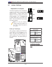
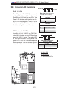
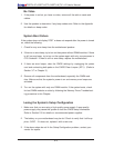
LAN 1/2
CTRL
10 Gb LAN 1/2
CTRL
BMC
CTRL
IOH 36D
Intel 82576
Intel 82599
Intel
ICH 10R
Intel
SAS
CTRL
LSI 2108
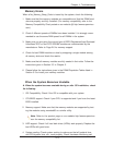
(10Gb LAN1)
(10Gb LAN2)
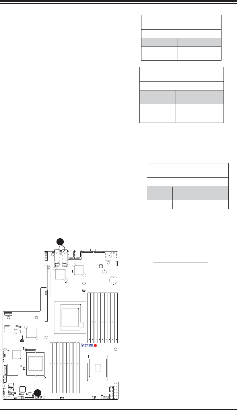
A
B
A. LAN LED
B. Onboard PWR LED
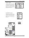
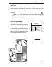
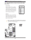
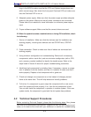
10Gb_LAN LED (X8DTU-6TF+)
A 10Gb_LAN LED is located at LED 7 on the
motherboard. When this LED color is in yel-
low, GLAN is connected and/or active. When
this LED color is in green, 10 Gigabit LAN
is connected and/or active. Please note that
the 10 Gb_LAN connections are available
on the X8DTU-6TF+ only. See the tables at
right for more information.
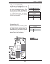
LAN LED (LED 7) In Yellow
LED States
Color/State Defi nition
Yellow: Blinking Gigabit LAN Active
Yellow: Solid On Gigabit LAN Link
(GLAN Connected)
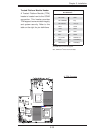
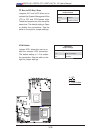
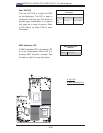
Onboard Power LED
An Onboard Power LED is located at LED1
on the motherboard. When this LED is lit,
the system is on. Be sure to turn off the
system and unplug the power cord before
removing or installing components. See the
table at right for more information.
Onboard PWR LED
LED Status
State/Color Defi nition
Off System Off (PWR cable
not connected)
Green System Power On
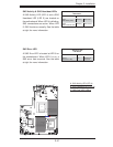
LAN LED (LED 7)-In Green
LED States
Color/State Defi nition
Green: Blinking 10 Gb_LAN Active
(X8DTU-6TF+ only)
Green: On 10 Gb_LAN Link (10
Gb_LAN connected)
(X8DTU-6TF+ only)