


Chapter 3: Installation
3-27
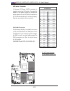
JPI2C1
FAN4
FAN6
FAN1
FAN2
J120
LED7
IPMB
UIOP
LED6
LED3
LED2
JWF1
SP1
JF1
I-SATA0
I-SATA1
I-SATA2
I-SATA3
I-SATA4
I-SATA5
JPW1
JPW3
X8DTU-6F+
JPTLAN
JPS1
JPG1
JWD1
TPM
JI2C1
JI2C2
JL1
JOH1
SAS4~7
SAS0~3
LED1
SAS BBU
Battery
USB0/1
USB7
USB6
USB4/5
COM2
UID
TLAN2
LAN2
IPMI_LAN
KB/MOUSE
FAN8/CPU1
FAN7/CPU2
P2-DIMM1C
P2-DIMM2C
P2-DIMM3C
P1-DIMM2C
P1-DIMM1C
P1-DIMM3C
J2: PCI-E 2.0 X16
P1-DIMM3B
P1-DIMM3A
P1-DIMM1A
P1-DIMM1B
P1-DIMM2B
P1-DIMM2A
P2-DIMM3A
P2-DIMM3B
P2-DIMM2A
P2-DIMM2B
P2-DIMM1A
CPU2
P2-DIMM1B
CPU1
LAN1
TLAN1
PHY
JPW2
T-SGPIO1
BIOS
COM1
VGA
JPL1
J1: PCI-E 2.0 X4 (in X16)
LED5
LED4
JBT1
T-SGPIO2
FAN5
FAN3
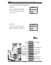
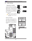
LAN 1/2
CTRL
10 Gb LAN 1/2
CTRL
BMC
CTRL
IOH 36D
Intel 82576
Intel 82599
Intel
ICH 10R
Intel
SAS
CTRL
LSI 2108
(10Gb LAN1)
(10Gb LAN2)
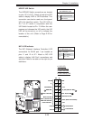
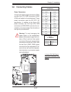
Warning! To avoid damaging the
power supply or the motherboard,
please use a power supply that con-
tains a 24-pin and two 8-pin power
connectors. Be sure to connect these
connectors to the 24-pin (JPW1) and
the two 8-pin (JPW2, JPW3) power
connectors on the motherboard. Fail-
ure to do so will void the manufac-
turer warranty on your power supply
and motherboard.
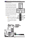
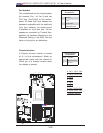
3-6 Connecting Cables
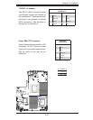
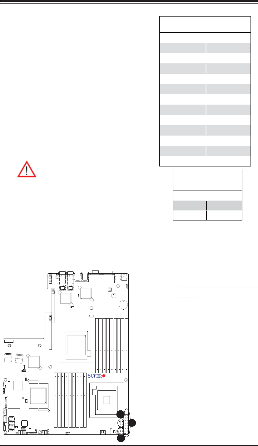
Power Connectors
A 24-pin main power supply connector (JPW1)
and two 8-pin CPU PWR connectors (JPW2/
JPW3) are located on the motherboard. These
power connectors meet the SSI EPS 12V
specifi cation. In addition to the 24-pin ATX
power connector, the 12V 8-pin CPU PWR
connectors at JPW2/JPW3 must also be con-
nected to your power supply. See the table on
the right for pin defi nitions.
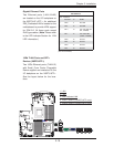
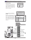
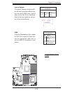
ATX Power 24-pin Connector
Pin Defi nitions
Pin# Defi nition Pin # Defi nition
13 +3.3V 1 +3.3V
14 -12V 2 +3.3V
15 COM 3 COM
16 PS_ON 4 +5V
17 COM 5 COM
18 COM 6 +5V
19 COM 7 COM
20 Res (NC) 8 PWR_OK
21 +5V 9 5VSB
22 +5V 10 +12V
23 +5V 11 +12V
24 COM 12 +3.3V
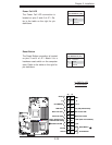
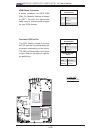
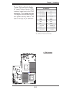
12V 8-pin PWR Con-
nector
Pin Defi nitions
Pins Defi nition
1 through 4 Ground
5 through 8 +12V
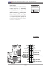
A. 24-pin ATX PWR (Req'd)
B/C.8-pin Processor PWR
(Req'd)
A
B
C
(Required)