


3-34
X8DTU-6F+/X8DTU-6TF+/X8DTU-6(T)F+-LR User's Manual
JPI2C1
FAN4
FAN6
FAN1
FAN2
J120
LED7
IPMB
UIOP
LED6
LED3
LED2
JWF1
SP1
JF1
I-SATA0
I-SATA1
I-SATA2
I-SATA3
I-SATA4
I-SATA5
JPW1
JPW3
X8DTU-6F+
JPTLAN
JPS1
JPG1
JWD1
TPM
JI2C1
JI2C2
JL1
JOH1
SAS4~7
SAS0~3
LED1
SAS BBU
Battery
USB0/1
USB7
USB6
USB4/5
COM2
UID
TLAN2
LAN2
IPMI_LAN
KB/MOUSE
FAN8/CPU1
FAN7/CPU2
P2-DIMM1C
P2-DIMM2C
P2-DIMM3C
P1-DIMM2C
P1-DIMM1C
P1-DIMM3C
J2: PCI-E 2.0 X16
P1-DIMM3B
P1-DIMM3A
P1-DIMM1A
P1-DIMM1B
P1-DIMM2B
P1-DIMM2A
P2-DIMM3A
P2-DIMM3B
P2-DIMM2A
P2-DIMM2B
P2-DIMM1A
CPU2
P2-DIMM1B
CPU1
LAN1
TLAN1
PHY
JPW2
T-SGPIO1
BIOS
COM1
VGA
JPL1
J1: PCI-E 2.0 X4 (in X16)
LED5
LED4
JBT1
T-SGPIO2
FAN5
FAN3
LAN 1/2
CTRL
10 Gb LAN 1/2
CTRL
BMC
CTRL
IOH 36D
Intel 82576
Intel 82599
Intel
ICH 10R
Intel
SAS
CTRL
LSI 2108
(10Gb LAN1)
(10Gb LAN2)
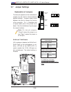
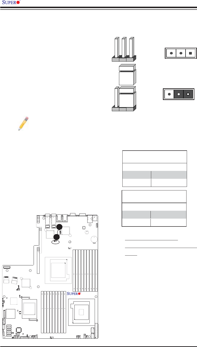
3-7 Jumper Settings
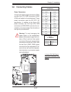
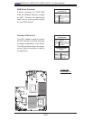
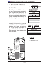
Explanation of Jumpers
To modify the operation of the motherboard,
jumpers can be used to choose between
optional settings. Jumpers create shorts
between two pins to change the function
of the connector. Pin 1 is identifi ed with
a square solder pad on the printed circuit
board. See the motherboard layout pages
for jumper locations.
Note: On two pin jumpers,
"Closed" means the jumper is on
and "Open" means the jumper is
off the pins.
Connector
Pins
Jumper
Cap
Setting
Pin 1-2 short
3 2 1
3 2 1
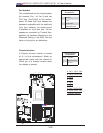
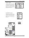
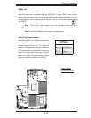
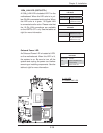
GLAN and TLAN Enable
JPL1 enables or disables the GLAN Port1/
GLAN Port2 on the motherboard. In ad-
dition, JPTLAN on the X8DTU-6TF+ is
used to enable the 10 Gb LAN ports on
this motherboard. The default setting is
Enabled.
GLAN Enable
Jumper Settings
Jumper Setting Defi nition
1-2 Enabled (default)
2-3 Disabled
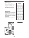
A
A. GLAN Ports 1/2 Enable
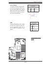
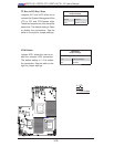
B. TLAN Ports 1/2 Enable (X8DTU-
6TF+)
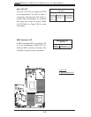
(10 Gb) TLAN Enable
Jumper Settings (X8DTU-6TF+)
Jumper Setting Defi nition
1-2 Enabled (default)
2-3 Disabled
B