


November 2001 Synopsys, Inc. 11
The ModelSource 640-pin Adapter Chapter 2: Building the Daughterboard
2
Building the Daughterboard
This chapter describes the specifications you must meet when building the
Daughterboard.
Daughterboard Description
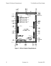
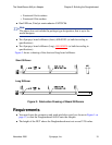
Figure 1 shows the physical specifications of the Daughterboard from the component
side. The Daughterboard is designed to have a footprint area in excess of 10” by 14”,
allowing for a multi-chip DUT.
Following are descriptions of some of the items shown on the drawing. All connectors
are to be installed from the far side.
● Guide pin holes: These are designed to mate with the guide pins on the Adapter to
ensure correct orientation when attaching the Daughterboard to the Adapter.
● Board stiffeners: Four (two long and two short) are required around the perimeter of
the Daughterboard to reinforce it. Fabrication drawings for compatible long and
short stiffeners are provided in Figure 3 on page 15.
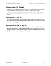
● Connectors J1-J6: These are to be installed from the far side, and are designed to
mate with corresponding connectors on the Adapter. The location of Pin A1 of each
connector is indicated on the drawing. Details of the connector pins are provided in
text that follows.