


November 2001 Synopsys, Inc. 13
The ModelSource 640-pin Adapter Chapter 2: Building the Daughterboard
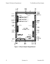
Connector Pin Detail
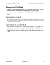
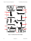
Connectors J1–J6 include the connections (DUT1–DUT640) between the DUT and the
Adapter through the Daughterboard and, in addition, supply voltage, ground
connections, and various auxiliary signals. Figure 2 shows details of J1–J6 connector
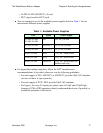
pins, from the component side. Pinouts are listed in “J1–J6 Connector Pinouts” on
page 29.
Connectors J1 and J3
These connectors include two each of Teradyne signal modules, and have 6 rows of 48
pins each. You will notice in Appendix A that no connections are listed for Rows B and
E; these are exclusively ground.
Connectors J2, J4, J5 and J6
These connectors include one each of Teradyne signal modules (A1–F24, at the left of
the figure) and two each of Teradyne power modules (AP1–FP4 and AP5–FP8, at the
right of the figure). As with connectors J1 and J3, the left (signal module) side has rows
B and E exclusively connected to ground. The right (power module) side has no rows B,
C, or E.