


November 2001 Synopsys, Inc. 17
The ModelSource 640-pin Adapter Chapter 2: Building the Daughterboard
❍ J4-FP5–J4-FP8 (FANP12V), if used
❍ DUT signal used for DUT clock
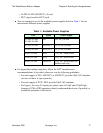
● You can connect to any of the available power supplies listed in Table 1. Do not
interconnect different power supplies.
● For bypass/decoupling capacitors, follow the DUT manufacturer’s
recommendations, if provided; otherwise, use the following guidelines:
❍ For each supply of P5V, ADJVCC1 or ADJVCC2, provide 47µF, 16V tantalum
(use two of these, if space permits).
❍ For each supply of P12V, M5V, provide 10µF, 16V tantalum.
❍ For bypass, for every 25 signal pins, place a pair of 0.1µF and 0.01µF high
frequency X7R or NPO capacitors directly underneath the device, if possible, or
around the perimeter of the device.
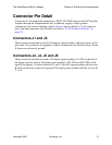
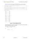
Table 1: Available Power Supplies
Pins Signal Power Supply
J2-AP5–J2-AP8
J4-AP5–J4-AP8
P5V +5V DC, 6A max
J2-AP1–J2-AP4 ADJVCC1 +3-5V DC, 6A max
J4-AP1–J4-AP4 ADJVCC2 +3-5V DC, 6A max
J4-FP1–J4-FP4 M5V -5.2V DC, 400mA max
J2-FP5–J2-FP8 P12V +12V DC, 400mA max
J4-FP5–J4-FP8 FANP12V +12V DC, 400mA max (for
fan/heat sink only)