


November 2001 Synopsys, Inc. 9
The ModelSource 640-pin Adapter Chapter 1: Describing a 640-pin Logic Model
1
Describing a 640-pin Logic Model
This chapter describes the necessary components and provides a procedural summary
for building a 640-pin Logic Model.
Hardware Requirements
To build a complete 640-pin Logic Model using the 640-pin Adapter, you need the
following hardware:
● The device you want to model, henceforth referred to as the device under test
(DUT). The DUT can have up to 640 input, output, and I/O signals, exclusive of
supply voltage and auxiliary signals. The DUT can include more than one physical
package, as long as the components fit within an area approximately 6” x 6”.
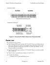
● One 640-pin Generic Device Adapter Daughterboard, henceforth referred to as the
“Daughterboard”, to which you attach the DUT.
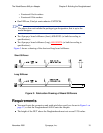
● Four ModelSource modeling systems, either 4 MS3200 units or 4 MS3400 units.
You cannot mix these two types of units.
● One 640-pin Adapter, which provides the interface between the modeling systems
and the Daughterboard.