November 2001 Synopsys, Inc. 19
The ModelSource 640-pin Adapter Chapter 3: Connecting the Daughterboard
3
Connecting the Daughterboard
This section describes the Adapter and gives instructions for interconnecting it and the
Daughterboard.
Adapter Description
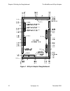
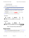
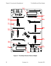
Figure 4 shows a drawing of the Adapter. The items of interest to the user are as follows:
● Connectors that mate with Daughterboard connectors J1–J6
● Ejectors for disconnecting the Daughterboard from the Adapter
● Guide pins that fit the Daughterboard guide pin holes to ensure correct orientation
● Test points for the signals TRIGGER, KEEPALIVE, PLAY, FEEDBACK,
SAMPLE, ADJVCC1, +5V, -5V, and GND


