14 Synopsys, Inc. November 2001
Chapter 2: Building the Daughterboard The ModelSource 640-pin Adapter
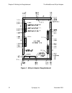
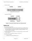
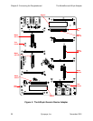
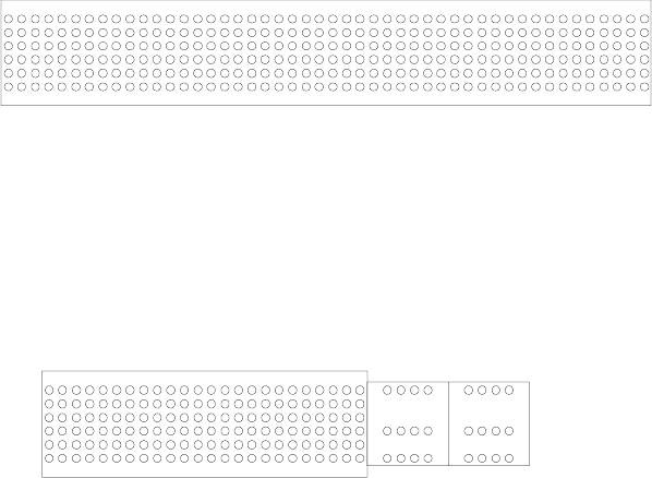
Figure 2: Connector Pin Detail, Shown from Component Side
Parts List
The required parts are as follows:
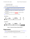
● Eight Teradyne HDM signal modules, 488-5324-XXX. These are available either as
press fit or solder tail, in a variety of tail lengths. The last three digits (XXX) of the
part number depend on which type you choose; for specific part numbers, see the
Teradyne product documentation.
● Eight Teradyne HDM power modules, 437-5034-500. These are currently available
only as solder tail.
● Twelve Southco retractable screw fasteners, 47-65-221-70.
● To mount the stiffeners:
❍ Fourteen 4-40 1/4” pan head Phillips screws
124
24
48
1
A
B
C
D
E
F
A
B
C
D
E
F
Connectors J1 and J3
Connectors J2, J4, J5 and J6
Rows B and E are connected to ground
One Teradyne
Signal Module
One Teradyne
Signal Module
One Teradyne
Signal Module
Two Teradyne
Power Modules
Rows B and E are
AP1 AP8
DP1 DP8
FP1 FP8
Rows B, C, and E
connected to ground do not exist


