


16 Synopsys, Inc. November 2001
Chapter 2: Building the Daughterboard The ModelSource 640-pin Adapter
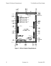
● The DUT signal traces (DUT1 through DUT640) are controlled impedance, and
must be 93 ohms ± 10%. (All other signals are uncontrolled but will function
correctly at 93 ohms.)
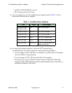
● You must make the following specific connections:
❍ J1-A1 to J1-F48 (SEAT1)
❍ J2-A1 to J2-F24 (SEAT2)
❍ J3-A1 to J3-F48 (SEAT3)
❍ J4-A1 to J4-F24 (SEAT4)
❍ J5-A1 to J5-F24 (SEAT5)
❍ J6-A1 to J6-F24 (SEAT6)
(These connections pass a daisychain signal through all four J connectors to allow
the ModelSource system to detect whether or not the Adapter is seated correctly.)
● You must provide a series termination of 4.7 ohms within 1 inch of the DUT’s signal
pins. Use as small a surface mount package as can practically be mounted.
Routing Guidelines
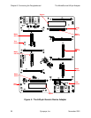
Provide connections for your DUT device(s) on the Daughterboard. Route the DUT
signals (DUT1 through DUT640) and other appropriate signals to the J connector pins
according to the pinout listing in “J1–J6 Connector Pinouts” on page 29.
The following are some guidelines:
● For optimal pattern clock rates, ensure that all DUT signals are the same length, or
nearly so (within 0.5 inch).
● Use either microstrip (preferred) or stripline for the signal layers, but do not mix
them, because their propagation velocities are different. Use microstrip if the signal
routing fits on two layers; use stripline if the signal routing requires more than two
layers.
● For ease of testing, create test points for the following signals:
❍ J1-D17 (KEEPALIVE)
❍ J1-A15 (TRIGGER)
❍ J1-A19 (PLAY)
❍ J1-A17 (SAMPLE)
❍ Any voltages used by the DUT