24
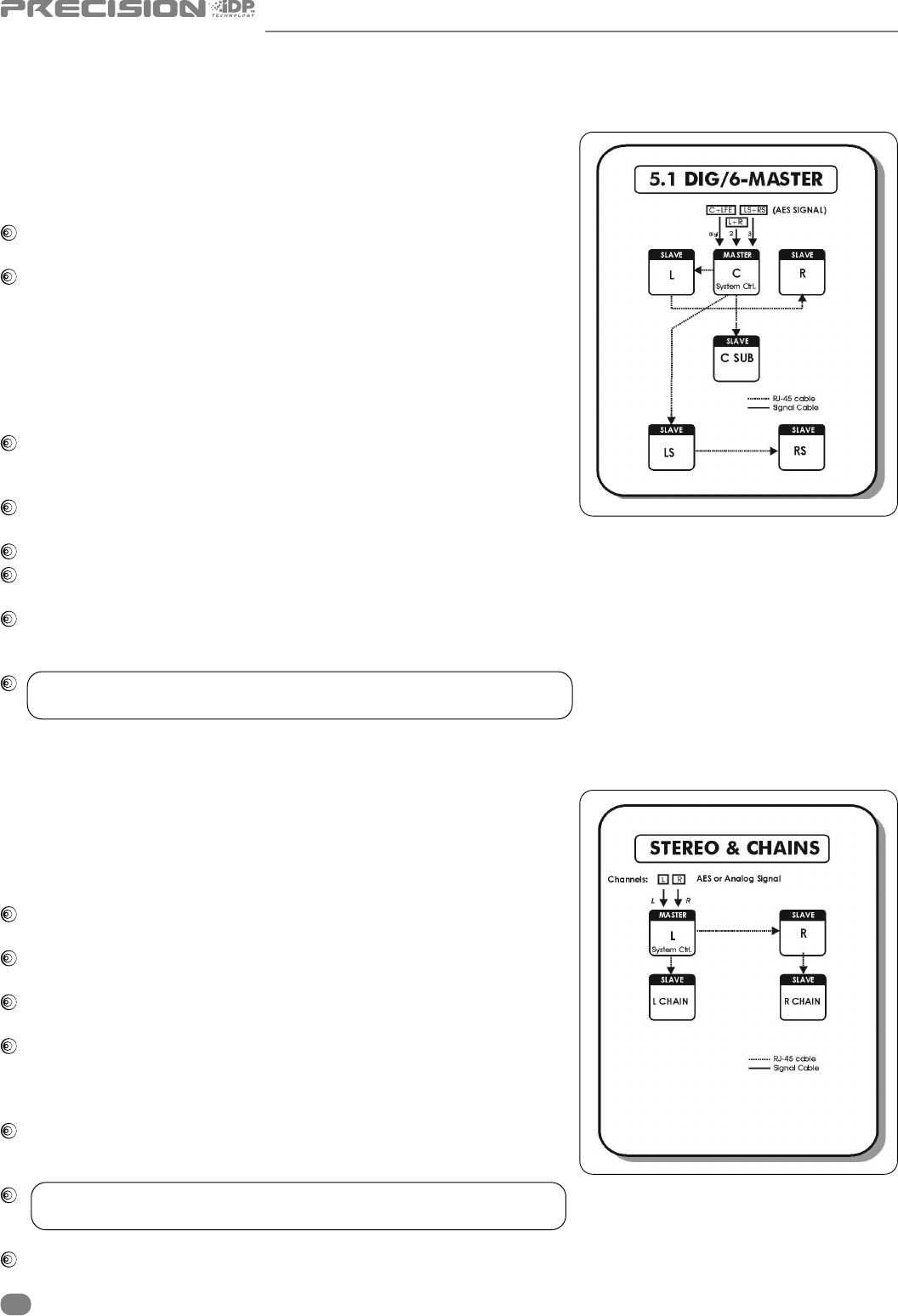
5.1 Dig/6 - Master
The diagram shows how to connect a 5.1 digital set-up using a single
master unit. The set-up requires one master monitor with the Digital
AES\EBU input card installed, four slave monitors and one subwoofer.
The Centre monitor is set as the System Controller by leaving out
the TC Link button on the rear panel.
The Centre monitor receives all six channels on the three AES\EBU
connections:-
Audio for the Centre and LFE channels are connected to the monitors
Digital IN connector.
Audio for the Left and Right channels are connected to the monitors
Digital IN No.2 connection on the I/0 card.
Audio for the LS and RS channels are connected to the monitors Digital
IN No.3 connection on the I/0 card.
RJ45 Network connections from the Centre monitor to the Left,
LS & subwoofer are required. Network connections from the Left to
Right, and LS to RS are required.
Clock MUST be sent on the AES/EBU connection feeding the
Centre/LFE channels (or on BNC)
When no Bass management is selected, only the LFE signal will be sent to the subwoofer.
When Bass management is selected, low frequency content from the
5 main channels is extracted and sent to the subwoofer where it is summed with the LFE channel
The iDP
™
Remote, iDP SOFT
™
or PC-iP
™
can be connected to any spare
TC Link “out” connection.
! REMEMBER – To set a master monitor as the system controller the
TC Link button on the rear panel MUST be in the out position.
Stereo Set-up With Chains on L&R. Analog or Digital
This diagram shows how to connect a stereo setup with chains on Left and
Right. The chained monitors are fed with the same signal as the front L&R
monitors. This is the type of setup you would use if you are alternating
between a set of main (Precision 8 iDP) and nearfield (Precision 6 iDP)
monitors. With this type of set-up only one master is required.
The Left monitor is set as the System Controller by leaving out the
TC Link button on the rear panel.
The Left master monitor receives both the left and right input signals
via the analog or AES\EBU input connector(s).
The Right monitor receives audio and control via the output RJ45
TC Link connections on the Left (system controller) monitor.
The Left monitor receives audio and control via the output RJ45 TC
Link connector on the Left (system controller) monitor.
The Right monitor receives audio and control via the output RJ45 TC
Link connector on the Right monitor.
The iDP
™
Remote, iDP SOFT
™
or PC-iP
™
can be connected to any
spare TC Link “out” connection.
! REMEMBER – To set a master monitor as the system controller the
TC Link button on the rear panel MUST be in the out position.
The “Chained” option is also achievable in all surround formats
ACTIVE STUDIO MONITORS


