


12 TASCAM US-1800
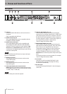
4 − US-1800 Control panel settings
Overview
The Control Panel lets you make various settings for the
US-1800’s functionality.
On Windows OS, the US-1800 Control Panel shortcut can
be found in the Windows Start menu > Control Panel or
the Start menu > All Programs > TASCAM. On Mac OS X, the
US-1800 Control Panel is located in the Applications folder.
Other useful audio and MIDI settings for Mac OS X can be
found in Applications/Utilities/Audio MIDI Setup.
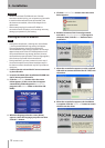
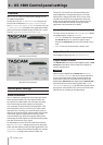
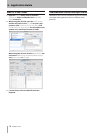
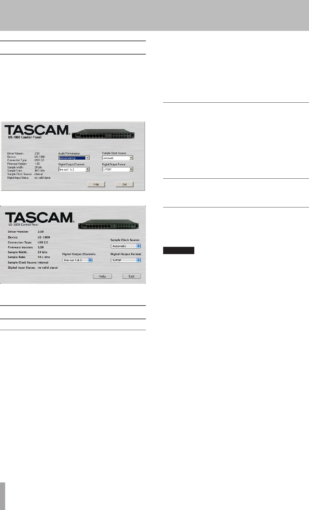
[Windows Control Panel]
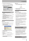
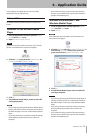
[Mac OS X Control Panel]
Control panel settings
Audio Performance
The US-1800 driver temporarily stores input and output
audio sample in buffers. The size of these buffers can
be adjusted. A smaller buffer size will reduce the delay
when monitoring the audio signal, but will require
your computer to perform the processing faster. If the
processing does not occur in time (e.g., if other system
operations are occurring), you may hear clicks, pops, or
dropouts in the audio signal. A larger buffer size provides
more safety against such problems caused by other
system activities, but will produce greater delay when
monitoring the audio signal. You should select the buffer
size that works best for your system.
On the Windows version of the US-1800 Control Panel,
the Audio Performance setting permits you to adjust the
buffer size that will be used by all audio applications. The
lowest latency setting is the minimum buffer size, and the
highest latency setting is the maximum buffer size.
On Mac OS X, the buffer size is determined by each
audio application. Consequently, there is no “Audio
Performance” setting on the Mac OS X version of the
US-1800 Control Panel. Some applications select the
buffer size automatically while others permit the user
to select the buffer size. Please consult your audio
application’s documentation for details.
Sample Clock Source
The clock source can be set to Automatic or Internal. When
using digital input, set this to Automatic.
Automatic
•
(default): If a clock signal is input through
the DIGITAL IN jack, it is used. If no signal is input
through the DIGITAL IN jack, this unit’s internal clock is
used.
Internal
•
: This unit’s internal clock is always used.
Digital Output Format
Set the digital output format to AES/EBU or S/PDIF.
Digital Output Channels
The DIGITAL OUT jack outputs either digital signals of LINE
OUTPUTS 1/2 or 3/4. You select which pair of signals to
output using this item.
CAUTION
When using the digital input (DIGITAL IN), set Sample
Clock Source to automatic, and set the connected device
as the clock master. Devices that cannot function as a
clock master cannot be used with this unit. When the
digital input (DIGITAL IN) and digital output (DIGITAL OUT)
are used at the same time, if the Control Panel Sample
Clock Source is set to internal, the DIGITAL IN signal cannot
be received, so the DIGITAL OUT sound is returned to the
DIGITAL IN as is, resulting in a feedback loop.