


14 TASCAM US-1800
5 −
Connections
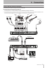
USB connections
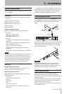
Using the included USB cable, connect the US-1800 to
your computer as shown in the illustration.
NOTE
Some USB devices access the USB bus frequently. In order
to avoid dropouts, clipping noise and other problems with
the audio signal, we strongly recommend that you do not
connect any other USB devices, with the exception of a
mouse and keyboard, to the same computer as this unit.
Audio connections
Connect the output signal of your mic, guitar, keyboard,
or other audio device to the US-1800, where it will be
converted into digital audio and sent via USB to your
computer. Connect the output of the US-1800 to your
speakers (via an amp) or headphones, so you will be able
to monitor the audio signals coming into the US-1800 or
being produced by your computer.
Use the MIX knob to adjust the balance between the
computer output signal and the input signals from
microphones, guitars and other connected equipment.
Mic
Connect your mics to the MIC IN (1-8) jacks (XLR) on the
front panel. If you are using a condenser mic that requires
phantom power, turn on the PHANTOM (+48V) switch.
You can use more than eight microphones by connecting
them via an external mic pre-amp. In this case, connect
the output of the mic pre-amp to the INPUTS (11-14) jacks
on the rear panel.
CAUTION
When the PHANTOM (+48) switch is ON, making an
•
unbalanced connection with a dynamic microphone
could cause the device to break.
Do not connect or disconnect any microphones when
•
the PHANTOM (+48) switch is ON. Doing so could cause a
loud noise or break the device.
Minimize the levels of the PHONES and MONITOR knobs
•
on the front panel before turning the PHANTOM (+48)
switch ON or OFF. Depending on the microphone, failure
to do so could result in a loud noise that might harm other
devices and damage human hearing.
Guitar
When connecting a guitar or bass guitar directly to this
unit, use a GUITAR/LINE IN (9-10) standard jack on the front
panel and set the GUITAR/LINE IN switch to GUITAR.
Analog connections with keyboards, drum
machines, sound modules and cassette,
MiniDisc and CD players, etc.
Connect the analog signal outputs of these types of
devices to the GUITAR/LINE IN jacks (9-10) on the front
panel or to the INPUTS jacks (11-14) on the rear panel.
When connecting them to the GUITAR/LINE IN jacks (9-10),
set the GUITAR/LINE IN switch to LINE IN.
NOTE
When a device is connected to a GUITAR/LINE IN jack
•
(9-10), you can use this unit’s gain control to adjust it in a
continuous range from –6 dBV to –52 dBV.
When a device is connected to an INPUTS jack (11-14), you
•
can set the nominal level to either –10 dBV (−10) or +4
dBu (+4).
Digital connections with sound modules and
MiniDisc and CD players, etc.
Connect the digital inputs and outputs of these types of
devices to the DIGITAL IN and OUT jacks on the rear panel
of this unit.
NOTE
This unit’s digital input is an RCA pin jack that accepts S/
•
PDIF signals.
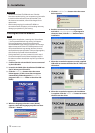
This unit’s digital outputs can output to either S/PDIF or
•
AES/EBU signals. Use the control panel to set the output
type.
Monitor speakers
Connect speakers for monitoring (powered speakers or an
amplifier and speakers) to the MONITOR OUTPUTS jacks on
the rear panel.
Headphones
Connect headphones to the standard stereo PHONES jack
on the front panel.
MIDI connections
Connect sound modules, keyboards, synthesizers, drum
machines and other MIDI devices to this unit as shown
in the illustration. MIDI signals input through the MIDI IN
connector on the rear panel of this unit are sent as is to
the computer. The MIDI signals sent from the computer to
this unit are output through the MIDI OUT connector on
the rear panel. As a result, by sending and receiving MIDI
time code (MTC), you can synchronize computer recording
software that is MTC-compatible with MIDI devices.