83
-
507
-
013 Rev. D
TABLE OF CONTENTS
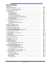
5.15.1 Basic parallel operation……………………………
………………………………………
Pg. 41
5.15.2 Advanced parallel operation………………………………………………………………
Pg. 42
5.16 DAISY
-
CHAIN SHUT
-
OFF CONNECTION…………………………………………………….
Pg. 45
5.17 FRONT PANEL LOCKING……………………………………………………………………….
Pg. 44
5.17.1 Unlocked front pan
el………………………………………………………………………
Pg. 44
5.17.2 Locked front panel…………………………………………………………………………
Pg. 44
CHAPTER 6 REMOTE ANALOG PROGRAMMING………………………………………………
Pg. 45
6.1 INTRODUCTION……………………………………………………………………………………
Pg. 45
6.2 LOCAL/REMOTE ANALOG CO
NTROL…………………………………………………………
Pg. 45
6.3 LOCAL/REMOTE ANALOG INDICATION……………………………………………………….
Pg. 45
6.4 REMOTE VOLTAGE PROGRAMMING OF OUTPUT VOLTAGE AND CURRENT………..
Pg. 46
6.5 RESISTIVE PROGRAMMING OF OUTPUT VOLTAGE AND CURRENT…………………..
Pg. 47
6.6 REMO
TE MONITORING OF OUTPUT VOLTAGE AND CURRENT………………………...
Pg. 48
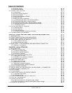
CHAPTER 7 RS232 & RS485 REMOTE CONTROL
……………………………………………...
Pg. 49
7.1 INTRODUCTION……………………………………………………………………………………
Pg. 49
7.2 CONFIGURATION………………………………………………………………………………….
Pg. 49
7.2.1 Default se
t
ting………………………………………………………………………………...
Pg. 49
7.2.2 Address se
t
ting……………………………………………………………………………….
Pg. 49
7.2.3 RS232 or RS485 sele
c
tion………………………………………………………………….
Pg. 49
7.2.4 Baud rate se
t
ting……………………………………………………………………
………..
Pg. 49
7.2.5 Setting the unit into Remote or Local mode……………………………………………….
Pg. 49
7.2.6 RS232/458 port at Local mode……………………………………………………………..
Pg. 50
7.2.7 Front panel in Remote mode……………………………………………………………….
Pg. 50
7.3 REAR PANEL
RS232/485 CONNECTOR……………………………………………………….
Pg. 50
7.4 MD MODE OPTION (Factory I
n
stalled)………………………………………………………….
Pg. 51
7.4.1 MD Mode Description……………………………………………………………………….
Pg. 51
7.4.2 MD Mode enable
-
Serial communication mode…………………………………
……….
Pg. 51
7.4.3 MD Mode SRQ……………………………………………………………………………….
Pg. 51
7.4.4 Communication Coll
i
sions…………………………………………………………………..
Pg. 51
7.4.5 MD Mode SRQ Retransmi
s
sion……………………………………………………………
Pg. 51
7.5 CONNECTING POWER SUPPLIES TO RS232
OR RS485 BUS…………………………….
Pg. 52
7.5.1 Single power su
p
ply………………………………………………………………………….
Pg. 52
7.5.2 Multi power supply connection to RS232 or RS485 BUS………………………………..
Pg. 53
7.6 COMMUNICATION INTERFACE PROTOCOL…………………………………………………
Pg. 53
7.6.1 Data fo
r
mat…………………………………………………………………………………...
Pg. 53
7.6.2 Addres
s
ing……………………………………………………………………………………
Pg. 53
7.6.3 End of message……………………………………………………………………………..
Pg. 53
7.6.4 Command r
e
peat…………………………………………………………………………….
Pg. 53
7.6.5 Chec
k
sum…………………………………………………………………………………….
Pg. 53
7.6.6 Acknow
l
edge………………………………………………………………………………….
Pg. 53
7.6.7 Error me
s
sage………………………………………………………………………………..
Pg. 54
7.6.8 Bac
k
space…………………………………………………………………………………….
Pg. 54
7.7 ERROR MESSAGES………………………………………………………………………………
Pg. 54
7.8 COMMAND SET DESCRIPTION…………………………………………………………………
Pg. 54
7.8.1 General guides……………………………………………………………………………….
Pg. 54
7.8.2 Command set categ
o
ries……………………………………………………………………
Pg. 54
7.8.3 Initialization control co
m
mands……………………………………………………………..
Pg. 55
7.8.4 ID control co
m
mands………………………………………………………………………..
Pg. 55
7.8.5 Output control co
m
mands…………………………………………………………………..
Pg. 55
7.9 GLOBAL OUTPUT COMMANDS………………………………………
………………………..
Pg. 57
7.9.1 Ge
n
eral………………………………………………………………………………………..
Pg. 57
7.10 SINGLE BYTE COMMANDS……………………………………………………………………
Pg. 58
7.10.1 Ge
n
eral………………………………………………………………………………………
Pg. 58
7.10.2 Global commands without r
e
sponse……………
………………………………………..
Pg. 58
7.10.3 Global commands with r
e
sponse…………………………………………………………
Pg. 59
7.10.4 Addressed commands with response……………………………………………………
Pg. 59
7.10.5 Addressed commands without response………………………………………………..
Pg. 59


