Getting Started
4
80A03 TekConnect Probe Interface Module Instruction Manual
Installing the TekConnect Probe Interface Module
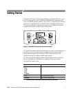
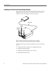
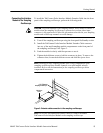
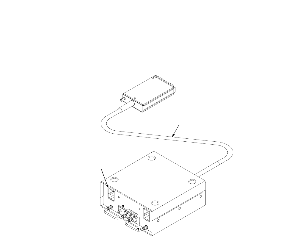
Figure 2 shows the TekConnect Probe Interface Module and locations of the
sampling module and probe inputs. The extender cable on the rear of the
interface connects to the sampling oscilloscope front panel.
Sampling
module
TekConnect
probe input
Extender cable
Semi-rigid
cable
Figure 2: TekConnect Probe Interface Module inputs and outputs
Installing the TekConnect P robe Interface Module consists of the following
steps:
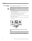
1. Connecting the Interface Module to the S ampling Oscilloscope.
2. Installing the Sampling Module.
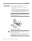
3. Installing the Semi-Rigid SMA Connector Cables.
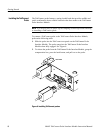
4. Installing the TekConnect Probe.


