


Table of Contents
ii
80A03 TekConnect Probe Interface Module Instruction Manual
List of Figures
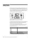
Figure 1: The 80A03 TekConnect Probe Interface Module 1........
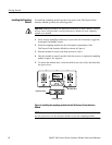
Figure 2: TekConnect Probe Interface Module inputs and
outputs 4...............................................
Figure 3: Extender cable connection to the sampling
oscilloscope 5............................................
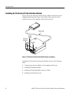
Figure 4: Installing the sampling module into the
TekConnect Probe Interface Module 6.......................
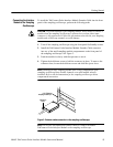
Figure 5: Connecting the sampling module 7....................
Figure 6: Installing TekConnect probes 8.......................
Figure 7: Equipment setup for functional check 10................
Figure 8: Removing the semi-rigid cable 15.......................
Figure 9: Setup for triggering the sampling oscilloscope
using the 80A03 TekConnect Probe Interface Module 16........
Figure 10: Trigger offset indicator 17............................
Figure 11: Setup for triggering the sampling oscilloscope
and viewing signals using the 80A03 TekConnect Probe
Interface Module 18.......................................
Figure 12: 80A03 replaceable parts 29...........................
List of Tables
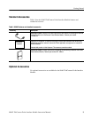
Table 1: 80A03 features and standard accessories 3...............
Table 2: Recommended equipment for performing a
functional check 9........................................
Table 3: Recommended equipment for triggering setup 14..........
Table 4: Electrical characteristics 23............................
Table 5: Environmental characteristics 23........................
Table 6: Physical characteristics 24.............................