Operating Basics
14
80A03 TekConnect Probe Interface Module Instruction Manual
Triggering the Sampling Oscilloscope
Use the following procedures to set up the 80A03 TekConnect Probe Interface
Module to trigger and view signals on CSA8000 and TDS8000 Series sampling
oscilloscopes.
The TekConnect P robe Interface Module supports many models of TekConnect
probes. Since the trigger bandwidth limit is determined by the probe bandwidth
and oscilloscope trigger capability, some probes may be more suitable than
others to your measurement needs.
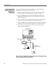
CSA8000 and TDS8000 Series oscilloscopes provide two trigger inputs you can
use with external probes, direct or prescaled. When selecting an input, you
should consider the frequency of the signal being measured. The bandwidth
specification of the measurement probe must also meet or exceed that of the
signal being measured.
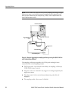
In addition, consider the following factors when setting up equipment to take
measurements:
H The oscilloscope trigger sensitivity relative to the amplitude of the signal
being measured.
H The probe scale factor.
H The attenuation factor of the power divider used, if you choose to view
signals on the oscilloscope following the trigger.
NOTE. Refer to your sampling oscilloscope documentation for direct and
prescaled trigger specifications.
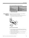
Refer to Table 3 for a list of equipment you need to implement the triggering
setups.
Table 3: Recommended equipment f or triggering setups
To trigger only To trigger and view a signal
Tekt ronix CSA8000 or TDS8000 Series
sampling oscilloscope
Tekt ronix CSA8000 or TDS8000 Series
sampling oscilloscope
Tekt ronix 80A03 TekConnect Probe Interface
Module
Tekt ronix 80A03 TekConnect Probe Interface
Module
Tekt roni x 80E02, 80E03, or 80E04 electrical
sampling module
Tekt roni x 80E02, 80E03, or 80E04 electrical
sampling module
Trigger Bandwidth
Considerations
Recommended Equipment


