


Operating Basics
80A03 TekConnect Probe Interface Module Instruction Manual
17
H You can view probe characteristics in the system properties menu for the
measurement channel.
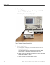
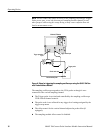
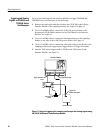
If you use the sampling oscilloscope Trigger Direct input, it is recommended that
you set the trigger level on the oscilloscope to 0 volts and control the trigger
level by directly assigning the vertical offset for the probe at the probe tip.
Because the offset control in the probe affects the signal level at its output, this
method of vertical offset adjustment provides calibrated trigger level operation.
To operate the offset control as a trigger level adjustment, rotate the offset adjust
on CH B. This will control the offset at the probe tip so you can read the trigger
level directly from the offset indicator on the sampling oscilloscope. See
Figure 10.
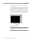
Read trigger level from
vertical offset value
Figure 10: Trigger offset indicator
NOTE. Rotation of the control knob for this configuration is reversed. Clockwise
rotation introduces a negative offset adjustment, which provides a negative
trigger level. Counterclockwise rotation introduces a positive offset and a
positive trigger level.