Operating Basics
80A03 TekConnect Probe Interface Module Instruction Manual
19
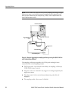
NOTE. Do not connect any other accessory to the sampling oscilloscope Trigger
Probe power port. Doing so may cause confusion that can lead to measurement
errors.
If you use the sampling oscilloscope Trigger Direct input, it is recommended that
you set the trigger level on the oscilloscope to 0 volts.
With this configuration, you can control the trigger level by directly assigning
the vertical offset for the CH B probe at the probe tip. Because the offset control
in the probe affects the signal level at its output, this method of vertical offset
adjustment provides calibrated trigger level operation.
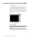
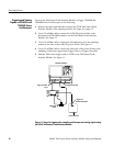
To operate the offset control as a trigger level adjustment, rotate the offset
adjustment on the sampling module channel that has the probe output discon-
nected. This will control the offset at the probe tip and you can read the trigger
level directly from the offset indicator on the sampling oscilloscope, as shown in
Figure 10.
NOTE. The 2X power divider used in this setup introduces a vertical scale error
factor of 2.
Sampling Module Incompatibility
Due to SMA cable incompatibility, you cannot directly use 80E01 or 80E06
sampling modules with the 80A03 TekConnect P robe Interface Module. See
page 2 for additional information.


