


Operating Basics
16
80A03 TekConnect Probe Interface Module Instruction Manual
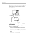
NOTE. Do not connect any other accessory to the sampling oscilloscope Trigger
Probe power port, or use the disconnected sampling module channel for any
other purpose while using this setup. Doing so may cause confusion that can
lead to measurement errors.
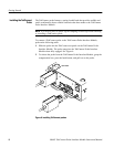
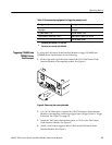
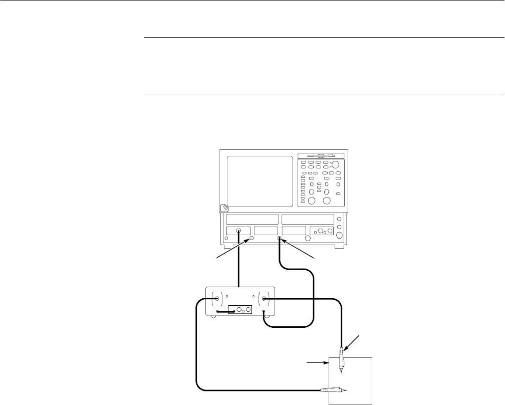
CSA8000/TDS8000
Trigger direct input
80A03
Trigger prescaled
input
Circuit under test
Trigger probe
Measurement probe
Figure 9: Setup for triggering the sampling oscilloscope using the 80A03 TekCon-
nect Probe Interface Module
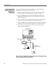
The sampling oscilloscope responds to the CH A probe as though it were
connected to the vertical sampling channel:
H The Trigger probe is serviced and controlled by the sampling oscilloscope
CH B vertical channel controls.
H The probe scale is not reflected in any trigger level settings assigned by the
trigger setup menu.
H The offset control for the vertical channel adjusts the probe offset (if
equipped).
H The sampling module offset control is disabled.