Getting Started
80A03 TekConnect Probe Interface Module Instruction Manual
7
To provide a signal path between the sampling module and the TekConnect
Probe Interface Module, perform the following tasks:
1. Connect your wrist strap to the antistatic connector on the front of the
sampling oscilloscope.
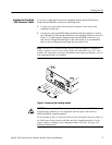
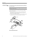
2. Use the two semi-rigid SMA cables (included with this product) to connect
the TekConnect P robe Interface Module to the sampling module as shown in
Figure 5. To obtain proper alignment and mate the SMA connectors, you
may need to change the bend angle of the center bend. It is recommended
that you do not change the bend angle by more than 1/8 in.
NOTE. Always use a calibrated torque w rench to install adapters, attenuators,
cables, or power sensors in any setup. Torque all connections to 8 ±0.3 inch
pounds. For information on proper installation and torquing techniques, refer to
your sampling module user manual.
Figure 5: Connecting the sampling module
CAUTION. The semi-rigid SMA connector cables used on the 80A03 TekConnect
Probe Interface Module are not compatible with the input connections of
80E01and 80E06 sampling modules.
Do not attempt to force a connection between the semi-rigid connector cables on
the TekConnect Probe Interface Module and these sampling modules. Use the
proper adapter or damage to the sampling module will occur. See page 2 for
additional information.
Installing the Semi-Rigid
SMA Connector Cables


