


Operating Basics
80A03 TekConnect Probe Interface Module Instruction Manual
15
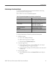
Table 3: Recommended equipment f or triggering setups (cont.)
To trigger only To trigger and view a signal
Compatible TekConnect probe.
See page 1.
Compatible TekConnect probe.
See page 1.
(1) SMA cable, 0.5 m
1
(3) SMA cabl es, 0. 5 m
1
Torque wrench, SMA 5/16, 8 in-lb Torque wrench, SMA 5/16, 8 in-lb
-- -- -- -- -- -- -- -- -- -- -- -- -- -- -- -- -- -- -- -- -- -- -- -- -- -- -- -- -- -- (1) 6 dB power divider
2
1
Tektronix part number 174-1427-00.
2
Tektronix part number 015-0565-00.
To set up the TekConnect Probe Interface Module to trigger CSA8000 and
TDS8000 Series Oscilloscopes, do the following:
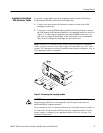
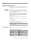
1. Remove the semi-rigid cable that connects the CH B TekConnect P robe
Interface Module to the sampling module. See Figure 8.
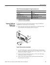
Figure 8: Removing the semi-rigid cable
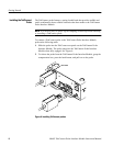
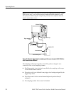
2. Use a 0.5 m SMA cable to connect the CH B TekConnect Probe Interface
Module to the sampling oscilloscope trigger input (Trigger Direct or Trigger
Prescaled). S ee Figure 9 on page 16.
3. Attach the TekConnect measurement probe to CH A on the T ekConnect
Probe Interface Module. S ee Figure 9.
4. Attach a TekConnect trigger probe to CH B on the TekConnect Probe
Interface Module. See F igure 9.
Triggering CSA8000 and
TDS8000 Series
Oscilloscopes