


124
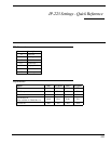
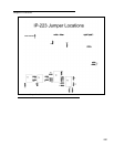
Jumper Settings
PCB 750743 or PCB 750630 revision F
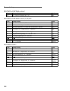
PCB 750743 or PCB 750630 revision C, D, E, and F
PCB 750630 revision A
Line 1 Jumper Setting Line 2
J35 "A" = RS232 serial data, "B" = TTL J26
Line 1 Jumper Setting Line 2
J33, J34 2 or 4 Wire, "A" = 2-wire, "B" = 4-wire J5, J6
J16, J21 RX Input, "A" = Single ended, "B" = Balanced J19, J20
J14 RX Input Impedance, “A” = 600, “B” = 8 and Center = 10Kohm J24
J3, J9, J11 TX Output, “A” = Single ended, “B” = Balanced
J25, J28,
J29
J13 TX Output Level, “A” = Low, “B” = High J27
J8 Digital I/O Pull-up Voltage, “A” = +5, “B” = +12 J30
J17, J22 TX Output Impedances: “B” = 600 ohms J10, J15
(J17
), J22 (“A”) and “B” = 1.2K ohms (J10), J15
J17, (J22
)“A” and (“B”) = 1.8K ohms J10, (J15)
J17, J22 “A” = 2.4K ohms J10, J15
Line 1 Jumper Setting Line 2
J33, J34 2 or 4 Wire, “A” = 2-wire, “B” = 4-wire J5, J6
J15, J16,
J21
RX Input, “A” = Single ended, “B” = Balanced
J19, J20,
J22
J14, J23 RX Input Impedances: “B” = 10K ohms J24, J17
(J14
), J23 (“A”) and “B” = 600 ohms (J24), J17
(J23
), J14 (“A”) and “B” = 8 ohm speaker (J17), J24
J3, J9,
J10, J11
TX Output, “A” =Single ended, “B” = Balanced
J25, J26,
J28, J29
J13 TX Output Level, “A” = Low, “B” High J27
J8 Digital I/O Pull-up Voltage, “A” = +5, “B” = +12 J30