


17
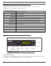
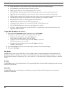
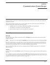
Front Panel
NOTE: Radio 1 and radio 2 are also referred to as line 1 and line 2 in this manual.
Handset Jack
An optional handset is available for the IP-223. When the optional handset is plugged into the handset jack, the ability to
monitor and talk on either line is available. The handset jack is located on the front of the unit, see Figure 78. When the
handset PTT switch is pressed, the selected radio connected to the IP-223 is keyed up on the existing frequency and the
handset microphone audio is transmitted.
Ethernet audio is also generated on the TX multicast and port for the selected line. This functionality can be used to test both
the Ethernet network and the analog connection.
IC Button
The IC button, when pressed, sends audio from the handset microphone back through the IP Network on the selected TX
multicast and port. It also sends audio to the transmit lines of the IP-223 without keying up the radio. This means no PTT relay
in local mode and no EIA (Electronic Industries Association) tones in tone mode.
NOTE: A handset is required to use the IC button.
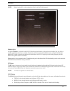
LCD Display
The LCD display provides panel status information, such as the IP and subnet addresses, line status, and handset line selection.
• TX F# (# is the selected function tone) indicates a PTT is active.
• RX F# (# is the selected function tone) indicates the RX radio is active.
• ID # displays when a Fleetsync or MDC ANI ID is decoded. This does not include serial decoding.
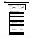
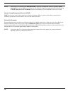
FIGURE 79. IP-223 Case Top Test Points