


31
Level Adjustments
General Alignment
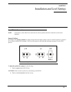
The IP-223 has a TX alignment tone and an RX alignment VU meter accessible from the front panel of the unit.
• Press and hold the line button and then momentarily press the IC button twice to generate the 1kHz 0dB TX
alignment tone on both lines.
• Press and hold the line button and then momentarily press the IC button three times to display the RX VU
meters.
Radio/Line TX Level
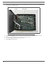
The Radio 1 TX test points (TP2 and TP6) and the Radio 2 TX test points (TP8 and TP9) are located on the front panel of the
IP-223. These provide a point to measure the actual signal being placed into the radio or balanced TX line. The front panel
accessible adjustment Radio 1 TX potentiometer (R47) and Radio 2 RX potentiometer (R61) are used to adjust these levels.
NOTE: If the unit is placed into single-ended mode, the radio TX+ should be measured with respect to ground.
It is also possible to place jumper J9 (line 1) or J26 (line 2) into the A position to decrease the output of the TX line by a factor
of 10. The final adjustment should allow for undistorted audio to be transmitted for the full range of transmission levels at the
desired deviation. This can be accomplished by turning on the TX alignment tone and adjusting the TX output to 0dB, as
measured into a 600 ohm load.
Radio/Line RX Level
Standard Alignment Procedure for a 2- or 4- wire System:
• Inject a 0dBm test tone on the RX pair (4-wire pins 12 and 24: 2-wire pins 13 and 25).
• Measure the RX level on test point TP13 for line 1 or TP1 for line 2.
• Adjust potentiometer R175 for line 1 or potentiometer R110 for line 2 until 0dBm is measured between the test
point and GND. (0dBM = 2VPP = .707VRMS)
• Detune slightly 1-2dBm to provide overhead for large transients.
• AGC (Automatic Gain Control) compression potentiometers RV5 for line 1 and RV1 for line 2 control the
aggressiveness of the AGC circuitry, if enabled. The AGC can be used to enhance the gain capabilities of the RX
circuitry. Set RV5/RV1 fully clockwise and, if required, back off 10 to15 degrees maximum.
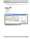
• Use the RX alignment tool (VU meter) accessed through the LCD display (press and hold the line button and
then momentarily press the IC button 3 times) to verify the dBm level. The reading should be 0dBm with the
AGC turned off. If the AGC is ON, it is likely the RX alignment software always displays 0dBm, the targeted
level for the AGC circuitry.
Line TX Monitor Level (Tone and Console Mode only)
PCB 750743 or PCB 750630 revision C and higher
The Line TX Monitor Level adjustment is used when the IP-223 is connected to consoles set in 4-wire mode. This allows for
local TX audio to be sent back on the Ethernet and played at other consoles so both sides of the radio traffic can be heard. The
alignment for TX monitor is similar to 4-wire RX alignment.