


Installation and Level Settings
26
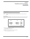
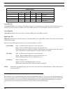
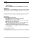
3. Carefully slide the case top forward past the IC and LINE buttons, and then lift up to gain access to the PCB (Printed
Circuit Board) as shown in Figure 83.
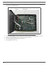
4. Locate the desired jumper on the PCB assembly and use needle nose pliers to adjust the jumper, if necessary.
5. Carefully lift up the case top and place it into position on the chassis bottom.
6. Secure the case top into position using the six (6) screws.
7. Connect power to the IP-223 unit.
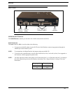
FIGURE 83. IP-223 PCB Assembly
Case top PCB assembly