6.5.7
Removing/Replacing DIMM Modules
To remove and replace DIMM memory modules, use the following procedure:
1. Loosen the keyboard assembly (but do not disconnect keyboard
cables) as described in Steps 1 through 4 of Paragraph 6.5.2.
2. Using the back edge of the keyboard as a hinge, lift the front edge of
the keyboard up and lay it against the LCD assembly.
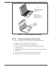
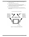
3. Push the two metal springs away from the board edge and remove the
DIMM board.
4. When installing a DIMM board, insert the edge of the board into the
rear of its connector using a slight rocking motion at an angle to the
surface of the board.
5. Once the DIMM is fully inserted in the connector, push downward on
both sides of the board to snap it in place.
6. Reinstall the Keyboard and replace components removed in Step 1.
6.5.8
Removing and Replacing the Display Assembly
To remove the display assembly, perform the following procedure:
1. Remove the keyboard and heat sink as described in Paragraphs 6.5.2
and 6.5.3 respectively.
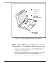
2. Remove the cable cover below the display by lifting upward on the front
edge of the cover.
3. Unplug the video cables that mate with the Main Board.
4. Using a plastic stick, slide the right and left hinge covers away from
the base assembly.
5. Lay the display completely back and remove the four screws that
secure the display hinges to the base case assembly
.
6. Observe cable routing and ensure that the display cables are free
from the top case assembly; remove the display assembly.
7. Reinstallation of the Display Assembly is the reverse of Steps 1
through 6 above.
6.5.9
Removing and Replacing the Inverter Board
or Contrast Board
To remove and replace either the Inverter Board or the Contrast Board,
perform the following procedure:
Field Service
6-13


