


6. Using a small flat blade screwdriver and apply light pressure in a
rocking motion to remove the hard drive cable connector.
7. Remove four Phillips-head screws (one on each of the four sides of the
heat sink opening) securing the board to the base assembly. Do not
remove the smaller screws which are part of the PCMCIA connector
hardware.
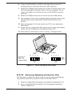
8. Remove the Phillips head screw at the left rear of the Main Board.
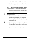
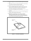
9. Lift up along the front edge of the Main Board Assembly until it clears
the hard drive cavity; then pull the board forward and out of the
plastics.
10. Refer to Paragraph 6.5.14 and transfer the CPU to the replacement
Main Board.
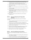
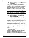
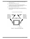
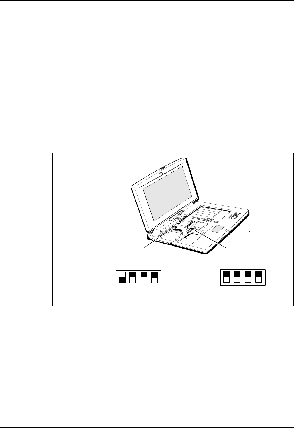
11. Inspect the two configuration DIP switches on the replacement board;
ensure that the settings are as described in Figure 6-5.
12. Reassembly is essentially the reverse of Steps 1 through 9 above.
6.5.14
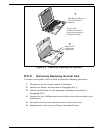
Removing/Replacing the Pentium Chip
The illustration in Figure 6-6 shows the procedure for removing/replacing
the processor from/to the processor socket on the Main Board.
1. Remove the Main Board assembly as described in Paragraph 6.5.13.
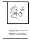
2. Insert a small flat-blade screwdriver into the rightmost opening as
shown in Figure 6-6.
ON
1
2
3
4
SW1
All
OFF
SW2
Switch 4
ON, all
others OFF
ON
1
2
3
4
Figure 6-5 Switch Settings for Main Board
6-16
Field Service