Getting Started With the Assembler and Linker
5-3
Getting Started With the Code Generation Tools
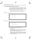
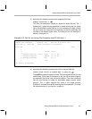
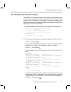
3) Now enter the following command to assemble file2.asm:
asm470 file2.asm –l
This time, the assembler creates an object file called file2.obj. The –l
(lowercase L) option tells the assembler to create a listing file; the listing
file for this example is called file2.lst. It is not necessary to create a listing
file, but it gives you information and assures you that the assembly has
resulted in the desired object code. The listing file for this example is
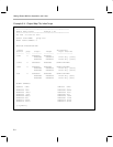
shown in Example 5–3.
Example 5–3. file2.lst, the Listing File Created by asm470 file2.asm –l
TMS470 COFF Assembler Version 1.20 Sat Feb 8 15:22:13 1997
Copyright (c) 1995–1996 Texas Instruments Incorporated
file2.asm PAGE 1
1
2 .global inclw
3
4 00000000 E2977001 inclw: ADDS r7, r7, #1
5 00000004 22966001 ADDCSS r6, r6, #1
6 00000008 E1A0F00E MOV pc, lr
7
8 .end
No Errors, No Warnings
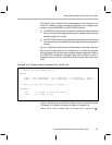
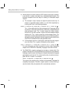
4) Now enter the following command to link file1.obj and file2.obj:
lnk470 file1 file2 –m lnker2.map –o prog.out
The lnk470 command invokes the linker. The input object files are file1.obj
and file2.obj. (If the input file extension is .obj, you do not have to specify
the extension; the linker uses .obj as the default.) The linker combines
file1.obj and file2.obj to create an executable object module called
prog.out. The –o option supplies the name of the output module.
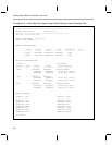
Example 5–4 shows the map file resulting from this operation. (The map
file is produced only if you use the –m option.)


