


MII-Enhanced Interrupt Event Feature
7-3
Physical Interface (PHY)
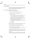
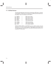
ThunderLAN implements the 19-signal MII shown in Table 7–1:
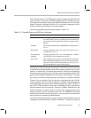
Table 7–1. ThunderLAN MII Pins (100M-bps CSMA/CD)
Name Type Function
MTCLK In Transmit clock: Transmit clock source from the attached PHY device
MTXD0
MTXD1
MTXD2
MTXD3
Out Transmit data: Nibble transmit data from ThunderLAN. When MTXEN is asserted,
these pins carry transmit data. Data on these pins is always synchronous with
MTCLK.
MTXEN Out Transmit enable: Indicates valid transmit data on MTXD[3::0]
MTXER Out Transmit error: Allows coding errors to be propagated across the MII
MCOL In Collision sense: Indicates a network collision
MCRS In Carrier sense: Indicates a frame carrier signal is being received.
MRCLK In Receive clock: Receive clock source from the attached PHY
MRXD0
MRXD1
MRXD2
MRXD3
In Receive data: Nibble receive data from the PHY. Data on these pins is always
synchronous to MRCLK.
MRXDV In Receive data valid: Indicates data on MRXD[3::0] is valid
MRXER In Receive error: Indicates reception of a coding error on received data
MDCLK Out Management data clock: Serial management interface to PHY chip
MDIO I/O Management data I/O: Serial management interface to PHY chip
MRST#
Out MII reset: Reset signal to the PHY front end (active low)
Communication with these devices is via the two MII pins MDIO and MDCLK.
The MDCLK signal is sourced from the host and is used to latch the MDIO pin
on the rising edge.
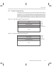
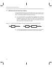
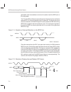
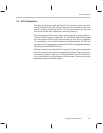
An MII frame consists of 32 bits, as shown in Figure 7–2 and Figure 7–3:
Figure 7–2. MII Frame Format: Read
Start
delimiter
Operation
code
PHY
address
Register
address
Turn-
around
Data
01 10 AAAAA RRRRR Z0 DDDD DDDD DDDD DDDD