


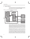

PCI Configuration Space
2-5
ThunderLAN Registers
Set up the PCI bus. Several PCI bus options can be selected through
these registers, including latency and grant. (Refer to
PCI Local Bus Spec-
ification,
subsection 3.5)
Map a BIOS ROM using the BIOS ROM base address register
Many of the registers in the PCI configuration space are accessed with PCI
BIOS calls. Refer to the
PCI Local Bus Specification,
chapter 6, for the com-
mands supported by your specific PCI BIOS. Some operating systems (O/Ss)
provide BIOS call support. Your operating system’s user’s guide contains
these specific BIOS support routines.
The PCI specification requires that a bus-resident device respond to bus cycle
codes reserved for reading and writing to configuration space. See the
PCI
Local Bus Specification
document for more information on how these short,
slot-dependent address spaces appear to the host processor. The shaded
registers in Figure 2–3 can be autoloaded from an external serial EEPROM.
Check the following before accessing the PCI configuration space:
Ensure that there is a PCI BIOS present or other support for BIOS calls.
Ensure that the BIOS is the right revision.
Use a PCI BIOS call to find all attached devices on the PCI bus. Make sure
that you are talking to the right device on the PCI bus.
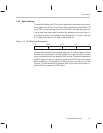
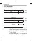
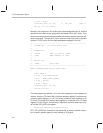
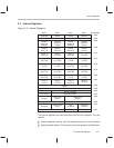
Attaching a pullup resistor to the EDIO pin allows the board designer to auto-
matically read an EEPROM after reset to determine the contents of the first
eight bytes, shown shaded below. If the host attempts to read any of the config-
uration space during the time the adapter is reading the EEPROM, Thunder-
LAN rejects the request by signaling target-retry.
Figure 2–3. Configuration EEPROM Data Format
Address
C8h
C7h
C6h
C5h
C4h
C3h
C2h
C1h
C0h
Checksum
Max_Lat
Min_Gnt
Subclass
Revision
Device ID MSByte
Device ID LSByte
Vendor ID MSByte
Vendor ID LSByte