


Adapter Host Registers
A-12
A.2 Adapter Host Registers
Host command registers contain bits which are toggled to tell the channel to
use receive or transmit FIFOs. ThunderLAN’s adapter host registers include
the adapter internal registers (see section A.3, Adapter Internal Registers).
The following subsections describe the functions of each host register accord-
ing to protocol.
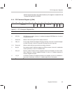
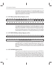
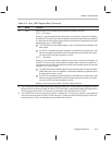
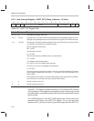
Figure A–3. Host Interface Address Map
offset
Base address
+12
+8
+4
+0
DIO_DATA
DIO_ADRHOST_INT
CH_PARM
HOST_CMD
0151631
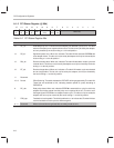
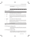
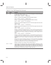
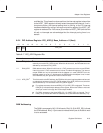
A.2.1 Host Command Register–HOST_CMD @ Base_Address + 0 (Host)
Ack Count
Reserved
on
Ints
off
Ints
Int
Req
Thr
Id
Tmr
Ld
Rst
Ad
00NesR/TEOCCh_SelAckStopGo
Byte 0Byte 1
Byte 2Byte 3
16171819202122232425262728293031
0123456789101112131415
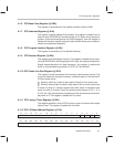
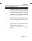
Table A–5. Host
_
CMD Register Bits
Bit Name Function
31 Go Channel go: This command bit only affects the network channels.
if R/T = 0 (Tx GO):
Writing a 1 to this bit starts frame transmission on a stopped or inactive channel.
Ch_Parm contains the address of the first transmit list.
if R/T = 1 (Rx GO):
Writing a 1 to this bit starts frame reception on a stopped1 or inactive channel. Ch_Parm
contains the address of the first receive list.
Writing a 0 to this bit has no effect. This bit is always read as a 0.
1) Frame transmission and reception are always placed in the stopped (reset) state after reset. therefore, no
frames are received into the Rx FIFO and no statistics are logged until the receiver has been started with
a GO command.