


PCI Configuration Space
2-4
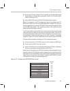
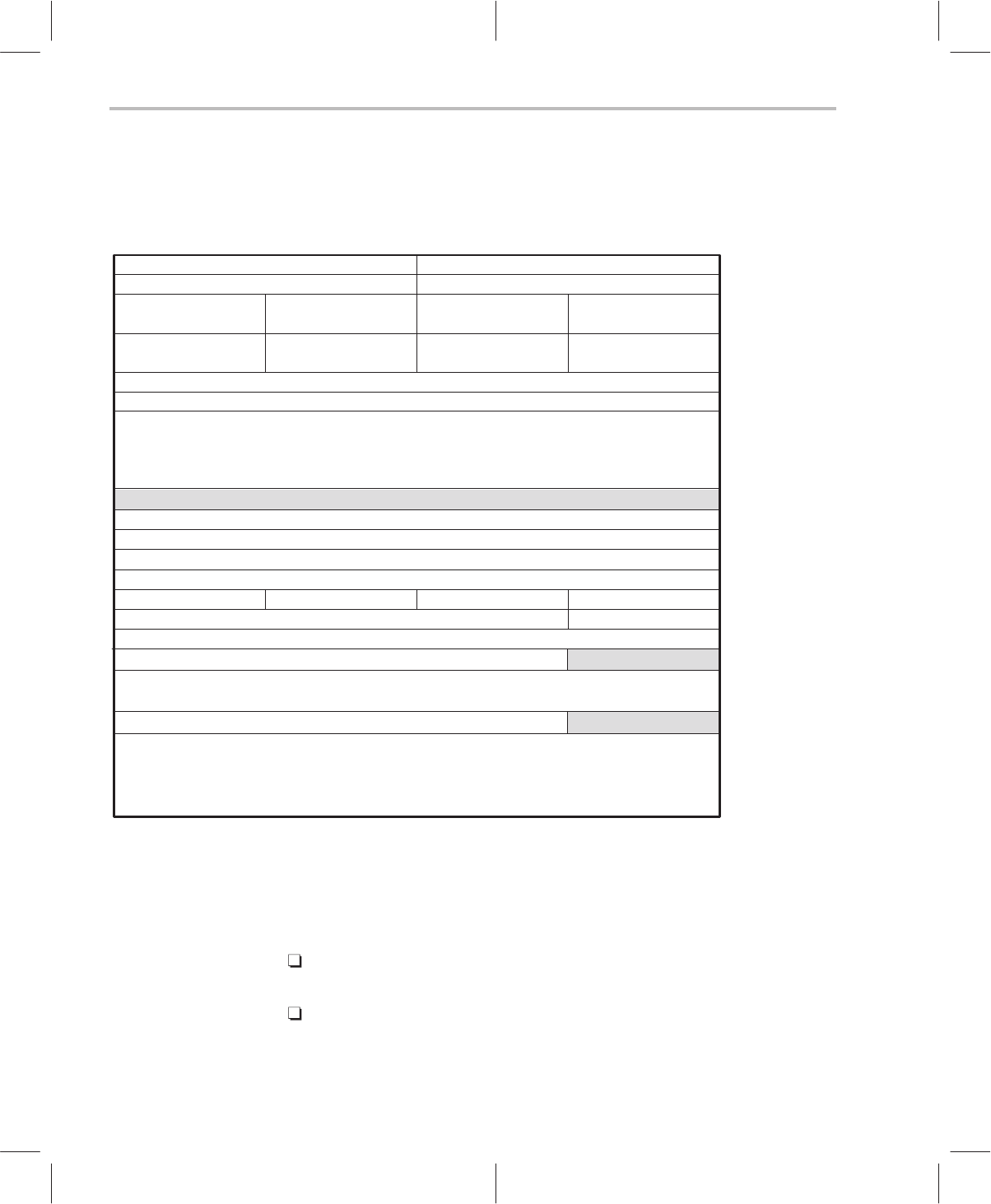
2.2 PCI Configuration Space
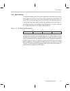
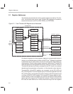
Figure 2–2. The PCI Configuration Space Registers
read only
read/write
read/write
read/write
read/write
read/write
read/write
read only
read/write
read only
Byte 0Byte 1Byte 2Byte 3
031
FFh
44h
40h
3Ch
38h
34h
30h
28h
18h
14h
10h
0Ch
08h
04h
00h
Reset control
Interrupt line
Int pin(01h)Min_GntMax_Lat
Reserved (00h)
BIOS ROM base address
Memory base address
I/O base address
size
Cache line
timer
Latency
Reserved
(00h)(00h)
Reserved
Revision
(00h)
Program interface
Subclass
(02h)
Base class
Vendor IDDevice ID
Status Command
Cardbus CIS Pointer
Reserved (00h)
Reserved (00h)
Reserved (00h)
Reserved (00h)
IntDis
Reserved (00h)
Reserved (00h)
PCI NVRAM
Reserved (00h)
48h
B4h
read only
2Ch
Reserved (00h)
Reserved (00h)
Register configuration space information fields are needed to identify a board
in a slot to a driver. The functional purpose of the board, the manufacturer, the
revision, and several bus requirements can be obtained by inspecting these
parameters. The PCI configuration space uses these registers which are
called out in the
PCI Local Bus Specification.
These enable the PCI system to:
Identify the ThunderLAN controller. This includes setting the interrupt as-
signed to ThunderLAN.
Map the host registers using either the I/O base address register or the
memory base address register. The driver uses the address contained in
these registers to access ThunderLAN’s internal registers.