


Toshiba Corporation Digital Media Network Company
Page 59 of 157
© 2005, Copyright TOSHIBA Corporation All Rights Reserved
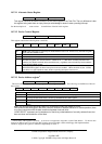
10.7.11 Alternate Status Register
- CS1 DA2-DA0 : 6 Read only
This register contains the same information as the status register in the Task File. The only difference is that
this register being read does not imply interrupt acknowledge or doesn’t reset a pending interrupt.
See the description of status resister for definitions of the bit in this register.
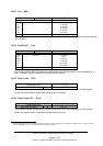
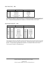
10.7.12 Device Control Register
- CS1 DA2-DA0 : 6 Write only
This register contains the following three control bits.
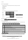
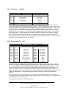
HOB ---- ---- ---- 1 SRST - IEN ----
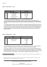
Bit 7
HOB (High Order Byte) is defined by the 48-bit Address feature set. A write to any Command register
shall clear the HOB bit to zero.
Bit 6-4 not used
Bit 3 Reserved (recommended to set 1)
Bit 2
SRST (Soft Reset) -- SRST= 1 indicates that the drive is held reset and sets BSY bit in Status register.
All internal registers are reset as shown in
Table 10.12-1 . If two drives are daisy chained on the
interface, this bit will reset both drives simultaneously , regardless of the selection by Device address
bit in DEVICE/HEAD register.
Bit 1
- IEN (Interrupt Enable) -- When -IEN = 0, and the drive is selected by Drive select bit in
DEVICE/HEAD register, the drive interrupt to the host is enabled. When this bit is set, the - INTRQ
pin will be in a high impedance state, whether a pending interrupt is found or not.
Bit 0 not used
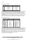
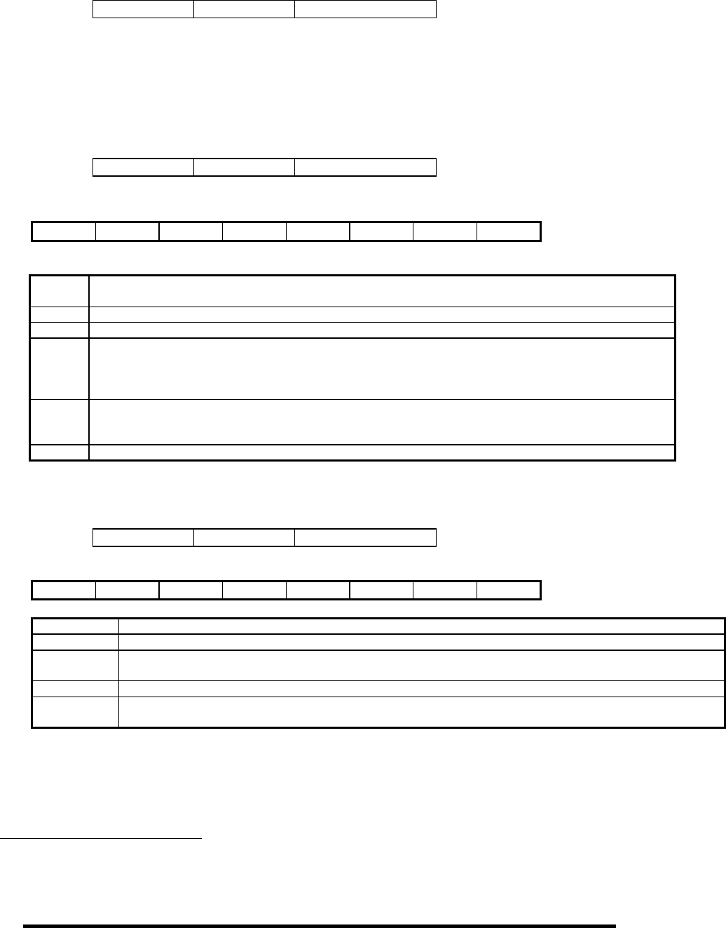
10.7.13 Device Address register
4
- CS1 DA2-DA0 : 7 read only
The device address register is a read-only register used for diagnostic purposes. The followings are definitions of bits for
this register:
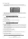
RSVD - WTG - HS3 - HS2 - HS1 - HS0 - DS1 - DS0
Bit 7 Reserved -- high impedance
Bit 6
- WTG (Write Gate) -- This bit is active when a Write to the disk is in progress.
Bit 5 - Bit 2
- HS3 to - HS0 (Head Select bits) -- Bit 5 through 2 are one's complement of the binary coded address of
currently selected head which is shown by Head Select bit in SDH register.
Bit 1
- DS1 (Drive Select 1) -- -DS1=0, when Drive1 is selected and active.
Bit 0
- DS0 (Drive Select 0) -- -DS0=0, when single mode or Drive0 in Drive0/Drive1 mode is selected and
active.
Note) The following facts should be taken into consideration when this resister is in use.
-WG reflects actual write gate in the drive, however, because of address transition or cache operation, there
is no direct connection with the data transferred between host and drive.
-HEAD SELECT represents one’s complement of the binary coded address of currently selected head, but
does not show actual selection of the head.
4
ATA-2 Notes: This register is obsolete. A device is not supposed to respond to a read of this address. If a device does
respond, it shall be sure not to drive the DD7 signal to prevent possible conflict with floppy disk implementations.
The drive supports this register to maintain compatibility for ATA-1.