


User’s Manual
13
1. AS311 Overview
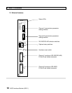
Hardware reset switch
When this switch is pressed, the AS311 will be reset. Use this switch when you
have changed the switch settings.
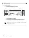
Channel 1 and channel 2 serial ports
Used to connect the serial transmission line (RS-232C or RS-422). D-Sub 25-pin
female connectors are provided on the AS311.
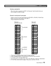
The pin assignment is as follows.
Channel 1 Channel 2
(RS-232C/RS-422) (RS-232C)
1 FG
↔
1 FG
↔
2 TXD
→
2 TXD
→
3 RXD
← for RS-232C
3 RXD
←
4 RTS
→
4 RTS
→
5 CTS
←
5 CTS
←
6 6 DSR
←
7 SG
↔
7 SG
↔
8 8
9 5 Vdc
→
9 5 Vdc
→
10 TXDA
→
10
11 RXDA
← for RS-422
11
12 RTSA
→
12
13 CTSA
←
13
14 14
15 15
16 16
17 17
18 18
19 19
20 DTR
→ for RS232C
20 DTR
→
21 TXDB
→
21
22 RXDB
← for RS-422
22
23 RTSB
→
23
24 CTSB
←
24
25 25
• The arrow on the above figure shows the signal direction.
• FG is connected with the T3’s frame ground internally. (both channels)
• DTR and RTS are ON while power is on.
• Data transmitting is available when CTS is ON. DSR has no effect for transmission.
• Pin 9 (5 Vdc) can be used to supply 5 Vdc power. (total max. 50 mA)