


User’s Manual
43
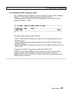
5. Operation Procedure
5.3 Write sequence for message transmitting
5.3.1 Flag control timing
In case of transmitting a message, the following flags are used for handshaking
between T3 and AS311. These flags are the bits of the I/O registers assigned to the
AS311. Refer to section 4.1.
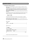
Write ready
Bit F of XW(n) for channel 1 or XW(n+1) for channel 2
Transmit complete
Bit E of XW(n) for channel 1 or XW(n+1) for channel 2
Transmit error
Bit D of XW(n) for channel 1 or XW(n+1) for channel 2
Transmit start
Bit F of YW(n+2) for channel 1 or YW(n+3) for channel 2
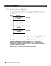
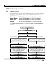
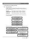
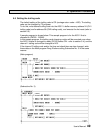
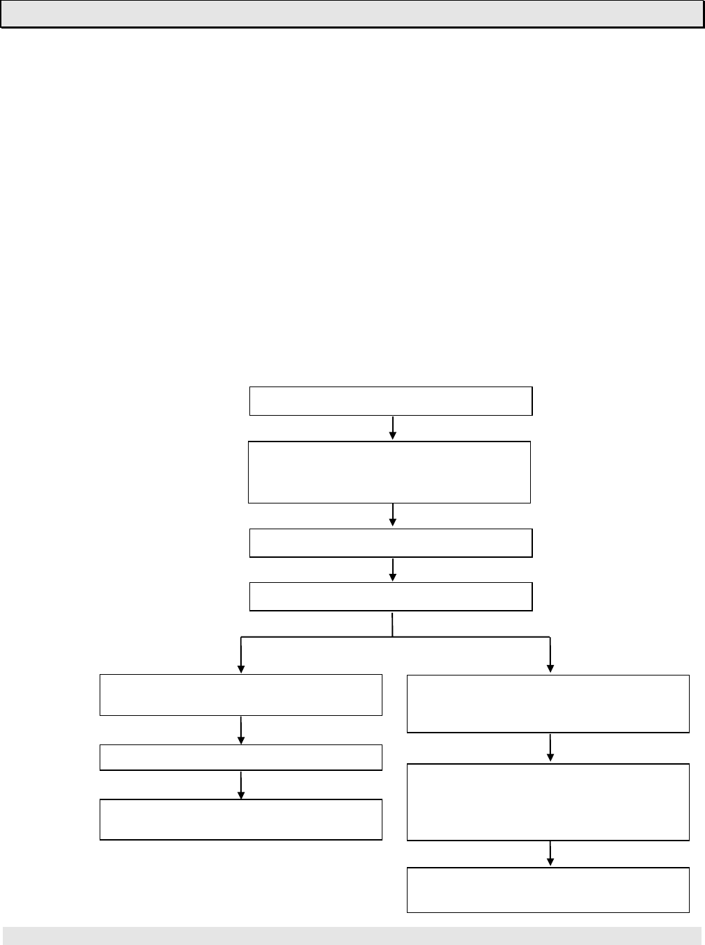
The message transmitting procedure is as follows. It is called “write sequence for
message transmitting”.
T3 checks Write ready is ON
T3 writes a message into buffer
memory (transmitting data area)
by WRITE instruction
T3 sets Transmit start to ON
AS311 resets Write ready to OFF
Normal transmitting Transmitting error
AS311 sends out the message and AS311 sets the error information into
sets Transmit complete to ON buffer memory (parameter area) and
sets Transmit error to ON
T3 resets Transmit start to OFF
T3 reads the error information from
buffer memory (parameter area)
AS311 resets Transmit complete to by READ instruction, and resets
OFF, and sets Write ready to ON Transmit start
to OFF
AS311 resets Transmit error to OFF,
and sets Write ready to ON