


24
ASCII Interface Module (AS311)
4. Register Configuration
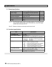
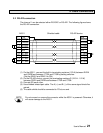
4.1 I/O allocation and I/O registers
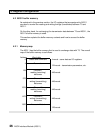
The AS311 has the I/O type ‘
i X+Y 4W
’ for I/O allocation. When the automatic I/O
allocation is performed with mounting the AS311, the following I/O allocation table will
be created in the T3.
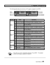
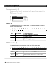
(T-PDS screen example - in the case that AS311 is mounted on Slot 0 of Unit 0)
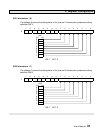
Then, 4 I/O registers, XW(n), XW(n+1), YW(n+2) and YW(n+3), are assigned to the
AS311.
In the above example, XW000, XW001, YW002 and YW003 are assigned.
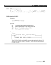
Note that the I/O type has ‘
i
’ designation. It means that the T3 will not update the
assigned I/O registers in the batch I/O processing. To read or write data through
the I/O registers, the Direct I/O instruction (FUN235) or the direct I/O designation
(I/IW and O/OW instead of X/XW and Y/YW) is necessary.
The reason of that is because the reading and writing timings are important for
handshaking between T3 and AS311. Refer to section 5.