


54
ASCII Interface Module (AS311)
6. RAS Information
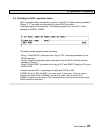
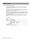
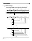
6.2.2 Switch setting status
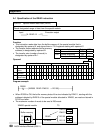
Addresses 5, 6 and 7 of the buffer memory store the switches setting status. Check
that the information agrees with the physical setting status if some abnormality has
occurred.
F E D C B A 9 8 7 6 5 4 3 2 1 0
5
0 0 0 0 0 0 0 0 RSW1 RSW2
Bit 7-4 RSW1 Stores the rotary switch 1 (RSW1) setting status.
0 - F
Bit 3-0 RSW2 Stores the rotary switch 2 (RSW2) setting status.
0 - F
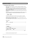
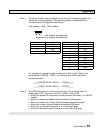
F E D C B A 9 8 7 6 5 4 3 2 1 0
6
0 0 0 0 0 0 0 0 SW1
SW1
OFF ON
8
7
6
5
4
3
2
1
ON: 1 OFF: 0
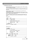
F E D C B A 9 8 7 6 5 4 3 2 1 0
7
0 0 0 0 0 0 0 0 SW2
SW2
OFF ON
8
7
6
5
4
3
2
1
ON: 1 OFF: 0