


User’s Manual
53
6. RAS Information
6.2 Buffer memory information
Various RAS information are stored in the AS311’s buffer memory. These information
can be read by READ instruction. When some abnormality has occurred, check these
information.
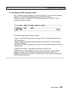
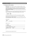
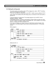
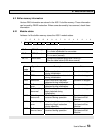
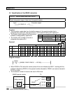
6.2.1 Module status
Address 4 of the buffer memory stores the AS311 module status.
F E D C B A 9 8 7 6 5 4 3 2 1 0
4
RDY ERR 0 0 0 0 0 0 Error code
Bit F RDY (Ready) 1 = operating normally
0 = under initialization or error state
Bit E ERR (Error) 1 = error state
0 = no error (normal)
Bit 7-0 Error code Shows the detected error item if ERR is 1.
See the table below (H00 when normal)
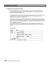
Error
code
Type of error Description Status
H01 CPU error CPU error has been detected
during initialization.
Operation is stopped.
H02 ROM error ROM error has been detected
during initialization.
Operation is stopped.
H03 RAM error Work RAM error has been
detected during initialization.
Operation is stopped.
H04 Buffer memory
error
Buffer memory error has been
detected during initialization.
Operation is stopped.
H05 Switch setting
abnormal
Switch setting abnormality has
been detected during
initialization.
Operation is stopped.
H10 Watchdog
timer error
Watchdog timer error has
occurred during operation.
Operation is stopped.
Cold reset will be
effective.
H11 Trap interrupt
error
Trap interrupt has occurred by
detecting illegal instruction
during operation.
Operation is stopped.
Cold reset will be
effective.
H12 Buffer memory
time-out error
Buffer memory time-out has
occurred during operation.
Operation is stopped.
Cold reset will be
effective.